Using the 2882 Hardware
2882 Front Panel
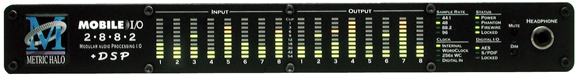
The 2882 front panel provides ten-segment metering for the 8 analog inputs and outputs. The meters are fast PPM peak reading meters with auto-resetting peak holds.
The front panel also provides 2882 system status at a glance:
- Sample Rate (nominal 44.1, 48, 88.2, or 96)
- The Sample Rate is determined from the currently selected clock source so it will accurately indicate the current sample rate, even when the clock source is being provided by an external device.
- Clock source:
- Internal indicates that the system is internally clocked
- Wordclock indicates that system is being clocked from the wordclock input
- 256x WC indicates that the system is being clocked from a 256x clock at the wordclock input
- Digital In indicates that the system is being clocked from the selected digital input (AES or S/PDIF)
- Power — Indicates that the 2882 is receiving power.
- Phantom power — Indicates that at least one of the preamps has the phantom power enabled.
- FireWire — Indicates that the 2882 has been successfully connected to a FireWire bus and has detected the isochronous cycle required to transmit and receive audio.
- Locked — Indicates that the system clock recovery circuit is properly locked to the selected clock source. If this light is not illuminated, the 2882 will not be locked to a clock and will revert to its failsafe internal clock source. Even if the Locked light is not illuminated, the actual sample rate will still be indicated on the front panel display.
- Digital I/O Section:
- The AES and S/PDIF lights are mutually exclusive and indicate which of the the two input ports are feeding the Stereo Digital input of 2882. The Locked light indicates when the digital receiver is locked to the incoming digital audio signal.
The Mobile I/O front panel also provides access to the Headphone output and some associated controls. The headphone output jack is a TRS 1/4” jack that provides the Left Channel on the tip, the Right Channel on the ring and the ground return for the two channels on the sleeve. These signals are all ground referred, so they may also be split and fed single-ended (unbalanced) to an external audio device.
The Mute and Dim buttons provide instant access to simple level control for the headphone output. The Mute button provides a quick, tactile “panic switch” which mutes the front panel headphone outputs in case of accidental feedback loops and other audio unpleasantries. The Dim button attenuates the front panel headphone output by 18 dB.
2882 Rear Panel
-
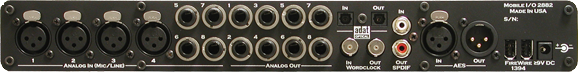
4 channels balanced XLR inputs. Each input has:
- 24-bit 96kHz A/D converters (110dB SNR)
- remote controllable pre-amps with 40 dB of gain
- remote switchable input impedance characteristics
- remote switchable 20dB pad
- remote switchable 48v Phantom power, with 10mA current limit
-
4 channels balanced TRS inputs. Each input has:
- 24-bit 96kHz A/D converters (110dB SNR)
- remote controllable pre-amps with 40 dB of gain
- remote switchable input impedance characteristics
- remote switchable 20dB pad
- remote switchable 48v Phantom power, with 10mA current limit
-
8 channels balanced TRS outputs. Each output has:
- 24-bit 96kHz D/A converters (120dB SNR)
- remote controllable output gain (from -12dBV up)
- TOSLINK connectors for ADAT Optical or Optical SPDIF I/O
- 8 channels of ADAT® lightpipe input (switchable to Optical SPDIF)
- 8 channels of ADAT® lightpipe output (switchable to Optical SPDIF)
- Wordclock input/output on BNC connectors
- 256x Wordclock input/output on BNC connectors
- Stereo S/PDIF input/output on RCA connectors
- Stereo AES/EBU input/output on XLR connectors
- 2 IEEE 1394 (FireWire) ports (400 Mbs)
- 1 2.1mm DC power jack (9v - 30v, center positive, 15 Watts)
Making connections to the 2882
There are six classes of connections you can make to the 2882 hardware:
- Analog Audio
- Copper-based Digital Audio
- Optical-based Digital Audio
- Clock Sync
- FireWire
- Power
ANALOG AUDIO CONNECTIONS
The analog I/O connections on the Mobile I/O have been engineered for maximum flexibility in that they support both balanced and unbalanced connections with a wide range of input and output levels and a wide range of matching impedances. This means that Mobile I/O handles sources from mic level to line level and from mic impedance to guitar impedance. With that in mind, there are a number of aspects of the design that you should take into account when interfacing with Mobile I/O.
Whenever possible, use balanced interconnects with Mobile I/O. The performance of balanced interconnects is much higher and much more resistant to noise interference and electrical (power) wiring problems. The expense of balanced interconnects is not substantially higher than unbalanced connections, so if the gear that you are interfacing with supports balanced connection — use it. If you cannot utilize balanced interconnects, there are connection schemes that you can use that will maximize performance.
On input, at line level, it is sufficient to simply use standard unbalanced (TS) connections. If you are interfacing with the Mobile I/O XLR inputs, you will need to ensure that pin 3 is grounded in the unbalanced adapter cable. More information about adjusting the input level can be found in the MIO Console software chapter.
The Mobile I/O XLR inputs are all wired pin 2 hot and the 1/4” inputs are wired Tip hot.
TIP: To use the 2882 TRS input with guitar or bass, you can simply use a standard TS guitar cable (patch cord) and it will work fine. However, you can take advantage of the balanced input design of the 2882 to get more noise rejection than you thought possible on a guitar input.
In order to do this, you will need to make a psuedo-balanced telescoping shield guitar cable. This can be constructed with a TRS connector, a TS connector and balanced microphone cable. This cable will treat the guitar as a floating balanced source and provide a telescoping shield from the 2882 ground.

If you want to use the TRS inputs with balanced microphones, you will need an XLR female to 1/4” TRS balanced plug adapter cable. These are available commercially, or you can construct one easily. The connections are Tip to Pin 2, Ring to Pin 3 and Sleeve to Pin 1:
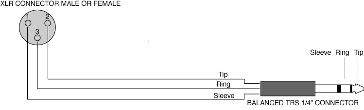
On output, the situation is a bit more complex. If you are driving an unbalanced load, you will get the best performance by not connecting the ring of the TRS jack to ground. In order to do this, you can simply use a balanced TRS/TRS connector with the unbalanced gear. You can also construct a special cable with a TRS connector and a TS connector. In this cable, you just let the ring of the TRS connector float:

Alternatively, the TS connector can be replaced with an RCA connector for interfacing with gear that has RCA unbalanced interconnects.
MAKING THE 1/4” CONNECTION
When you connect a 1/4” plug to a 2882 jack, insert it straight and firmly, ensuring that the plug is fully inserted into the jack. If the plug is not fully inserted you will get level shifts, phase flips, distortion, or no sound.
To disconnect a 1/4” plug, firmly pull the plug straight out from the connector body. The connectors on 2882 are stiff, so you may have to exert some force to remove the plug.
MAKING THE XLR CONNECTION
When you connect a Male XLR plug to a 2882 jack, ensure that you have aligned the pins with the connector body and insert firmly until the retention tab clicks.
To disconnect the plug, press the metal retention tab flush against the box, and pull the plug from the 2882.
COPPER-BASED DIGITAL AUDIO
2882 supports 2 channels of digital audio over copper-based connections. These connections can be made using either S/PDIF interconnects with the RCA connectors or with AES interconnects using the XLR connectors. Even though only one of the AES or S/PDIF inputs can be active at any given time, you can have different digital sources connected to each of the input connectors at the same time – you use the MIO Console application to select the active input. Audio routed to the digital outputs will be mirrored by both S/PDIF and AES outputs. This allows you to send the same stereo pair to two devices at once.
We recommend that you use the AES interconnect mechanism to establish the digital communication between the 2882 and other digital devices. The jitter and electrical noise tolerance on AES interconnects is substantially better than with S/PDIF interconnects. The AES interconnect standard is equivalent to balanced audio interconnections. If you need to use S/PDIF interconnects, try to use the shortest cables you can and, if possible, use special purpose 75 ohm S/PDIF or video cables.
The RCA connectors used for S/PDIF are friction fit coaxial connectors. When you connect them, ensure that they are fully inserted and tight.
The XLR connectors used for AES are fully locking. When connecting to them, make sure that you align the pins and insert firmly. When you remove the connector, make sure that you release the lock by pressing the lock release button before you pull the connector out of the 2882.
INTEGRATED SRC
Normally, when working with digital audio transport, you must take care to ensure that all devices communicating with one another are synchronized to the same audio clock. While this is still an important consideration with 2882, the hardware provides a special feature to simplify copper-based digital connections to the box. The digital input on 2882 has an optional asynchronous sample rate converter (SRC) that will automatically match the sample rate of the incoming audio to the sample rate of the 2882. This converter is enabled by default and you can disable it in the System section of the MIO Console. If you have synchronized the 2882 to the external source (using any of the extensive synchronization methods provided by 2882), you will generally want to disable the SRC in order to get 24-bit transparent audio transport over the digital input.
OPTICAL-BASED DIGITAL AUDIO
Mobile I/O provides two TOSLink™ connectors on the back panel. One is a transmit connector and the other is a receive connector. These connectors are used with Plastic Optical Fiber (TOSLink) cables to communicate with other devices. The TOSLINK connectors can be used to communicate with either the ADAT® Optical communication protocol or the Optical SPDIF communication protocol. Each port can be indpenedently switched between the two protocols via MIO Console.
The ADAT Optical standard allows a device to transmit 8 channels of 24-bit audio at up to 50kHz along with digital audio clock information.
The Optical SPDIF communication protocol allows a device to transmit 2 channels of 24 bit audio at 96kHz, along with digital audio clock information.
Since Mobile I/O provides direct routing within the box, you can easily configure the unit to work as an ADAT based 8 channel A/D/A. Refer to the chapter on MIO Console for information about configuring the routing.
CLOCK SYNC
Clock sync is a serious consideration in any digital audio system.
If you are recording analog sources with 2882, you can simply use the unit’s high-quality internal clock source to drive the converters. This is the easiest case to deal with.
If you need to interface with other devices digitally or ensure sample accurate sync with video sources, the extensive clock synchronization capabilities of 2882 will prove to be more reliable (and better sounding) than most higher priced alternatives.
There are four different ways to get external clock information into the unit:
- Sending a 1x word clock signal into the WC Input BNC.
- Sending a 256x word clock signal into the WC Input BNC.
- Sending an AES or S/PDIF signal into the Digital input.
- Sending an ADAT signal into the Optical Digital input.
The BNC word clock input port is a 75 Ohm terminated coaxial input. It should be driven by a 75 Ohm source driver and interconnected with 75 Ohm coaxial cable. If you do not use proper cabling and source drive, you will introduce reflections on the word clock cable which will propagate jitter into the recovered word clock. This is true whether you use the port as a 1x WC input or a 256x WC input, but becomes more important when the clock signal is 256x.
1x is generally appropriate for use with devices that provide a word clock output. If your device provides a 256x output, you may find that you get better results using that clock signal. The Digidesign® line of Pro Tools® products use 256x as their “ SuperClock™” clocking signal.
The AES recommended procedure for distributing clock is to use an AES clock signal. The AES clock signal is an AES digital audio signal with no audio activity. 2882 only uses the AES preambles for clock recovery, so it is immune to data dependent jitter effects. This means you can reliably use the Digital Input as a clock source with or without audio data.
FIREWIRE
FireWire® is Apple’s registered trademark for the IEEE 1394 High-Speed Serial Bus. FireWire started as an Apple technology to replace a variety of interface ports on the back of the computer. After promulgating a number of closed proprietary technologies in the early days of the Macintosh, Apple determined that open standards were better for the Mac, for the industry, and for Apple itself. On that basis they opened their technology for standardization under the auspices of the Institute of Electrical and Electronics Engineers, Inc. (IEEE), an international organization that promotes standards in the field of electronics. FireWire was standardized as IEEE 1394 and promoted for open licensing in the industry.
The first widespread adoption of the technology was for DV camcorders where space was at a premium and bus powering was not perceived as a real issue since all camcorders have batteries. Sony designed an alternative version of the standard 6-pin FireWire connector that provided 1394-based communication with 4-pins in a much smaller form-factor. This version of the connector sacrificed bus-power support and mechanical stability for reduced space requirements. Sony dubbed this version of IEEE 1394 “i.Link®.” This became the de facto standard in the DV world, and was later added to the IEEE 1394 standard. Both i.Link and FireWire refer to the same underlying standard and are completely interoperable. Obviously, i.Link connectors and FireWire connectors cannot be used together without adapters.
2882 uses the FireWire flavor of the IEEE1394 connector with 6-pins for bus power support. The unit ships with two 6-pin to 6-pin FireWire cables, one that is 0.5 meters long (about 18 inches), and the other 4.5m (about 14.5 feet) long. If you want to use 2882 with a 4-pin FireWire device, you will need to purchase a 6-pin to 4-pin adapter cable. These cables are available from a wide variety of retail sources. If you are using a 4-pin cable to connect any device to the computer with 2882, bus power will not be available.
The 6-pin FireWire connector is polarized by its shape, one end of the connector is pointed. The FireWire ports on 2882 point downwards toward the bottom of the box. It will be very difficult to insert the connector upside down, but it is possible if you force it. If the plug is inserted into the socket upside down, the socket will be destroyed. NEVER FORCE A FIREWIRE CONNECTOR INTO A FIREWIRE SOCKET.
Devices connected to the FireWire bus are autoconfiguring. You do not need to set IDs or DIP switches or in any way configure the devices in order to facilitate communication between devices or to configure the bus.
FireWire devices on the same bus must be connected in a tree structure with no loops. This means that devices can be connected to each other in any order, and any device with multiple ports can act as a chain or a hub for other FireWire devices, but you should never be able to get from one device to another by more than one path. If you construct a loop in the bus, it will not operate properly and you will not be able access some or all of the devices on the bus.
Although you are able to attach devices in any order on the FireWire bus, the order of attachment will have an impact on performance. Most current model FireWire devices support 400 Mbs operation, but many older devices may only support 100 or 200 Mbs operation. These devices act as a bottleneck in the bus and limit the speed of any bus traffic that flows through them. In order to maximize performance, you want to ensure that low speed devices are not used to join high speed devices. In practice this generally means that you should attach your 2882 directly to your computer or through a high speed hub.
To connect 2882 to your computer simply plug a FireWire cable into the 2882 and into the computer. The FireWire bus provides a path for all communication between the computer and 2882 – audio, control and meter data.
2882 audio transport takes advantage of FireWire’s support for isochronous transmission, in which the 2882 can reserve a dedicated amount of bandwidth on the bus for moving audio samples. Since the audio must be transmitted on a regular basis to ensure continuous playback and recording , the isochronous model is perfect.
Control changes and meter data are transmitted using asynchronous transactions on the FireWire bus. This transmission approach makes use of the unreserved bandwidth on the bus and competes with things like FireWire hard disk accesses for time. Under normal circumstances this is completely transparent to the user. If the bus becomes overloaded, you may find that disk accesses and meter updates slow down. If you are experiencing bus overloads, you can always add a second FireWire bus with a third-party FireWire card (PC-Card or PCI card depending on your machine), and offload one or more devices to the second bus.
POWER
One of 2882’s great strengths is the flexibility of its power system. 2882 can be powered from any DC source (including bus power) in the range of 9V to 30V as long as it provides 12 Watts of power. The DC inputs on 2882 are a 2.1mm coaxial power connector, center positive and a 4-pin XLR connector Pin 4 Hot. So if you are powering the unit with a third party power source and it supplies 9V, the power source will have to provide 1.4 amps of current. If you are powering the unit with 12V, the power source will have to provide 1 amp of current, and so on.
The 2882 ships with a world-ready 24 volt, 2 amp power supply. You can plug this supply into any AC power source from 90V to 240V, 50Hz - 60Hz, using an appropriate IEC power cord, and it will supply the proper power to the 2882 on the 2.1mm coaxial power connector. 2882 will automatically supply the extra power to the FireWire bus. This means that the 2882 and its power supply can be used to power other bus-powerable FireWire devices including hard-drives, hubs, and other 2882 units.
Since 2882 is DC powered, you can also power up the 2882 using the FireWire bus or another DC source. The 2882 uses 12 Watts of power, so the device supplying the bus power must be capable of sourcing that much power. Most desktop Macs provide more than enough power for 2882 and one other low power device. Most laptops provide enough power for 2882, but not enough for 2882 and another bus-powered device at the same time. If you are using a Powerbook computer, you should not expect to be able to power both the 2882 and a hard drive from the computer. The power capabilities of individual computers vary, so you will have to test the complete system to determine exactly how much your computer can handle.
If you find that the computer is not capable of powering 2882 or does not provide enough run time, you may want to explore using an external power source with the 2882. Check with Metric Halo for details on different battery power solutions for 2882.
As with all electronic devices, when connecting an external power source to the 2882, you should first connect the power source to 2882 while it is in an unenergized state (e.g. not connected to the mains or switched off). After the connection to 2882 has been made, you should energize the power source.
If you connect an energized power source to the 2882’s 2.1mm power connector you may see a small spark when you make the connection. This is due to surge current and is normal if you connect a power source in this way. While this will not damage the 2882 in any way, to avoid the spark just connect the power connector to 2882 before connecting the power source to the wall.