Monitor Controller
The Monitor Control window consolidates the most important monitoring functions for your MIO into one convenient window. You can configure which sources you want to monitor and from which outputs they will be monitored, for any number of channels from mono to 7.1 Surround. You can configure the Monitor Controller as a floating window so it always remains accessible, even when the MIO Console is hidden. You can choose between the full size Monitor Control window and a smaller Mini Controller window that contains nearly all the functions of its big brother. Finally, as an optional component of the MIO Console, if the Monitor Controller simply doesn’t fit into your workflow, you don’t need to use it.
Ultra-Quick Start Guide to Configuring the Monitor Controller
If you just want to set your main outputs of your Mix Bus to be controlled by the monitor controller, follow the steps below:
To Add the Bus Output of your Mix Bus to the Monitor Controller:
- In the Master strip for your Mix Bus in the v.5 mixer, click the Bus Output pop-up menu.
- Select Add to Monitor Controller. The Bus Output of your Mix Bus is now automatically configured as the Monitor Source for the Monitor Controller.
To Configure the Monitor Controller:
- Select Window > Show Monitor Controller.
- Click the Configure button at the bottom of the Monitor Controller window. The Configure Monitor Controller sheet appears:
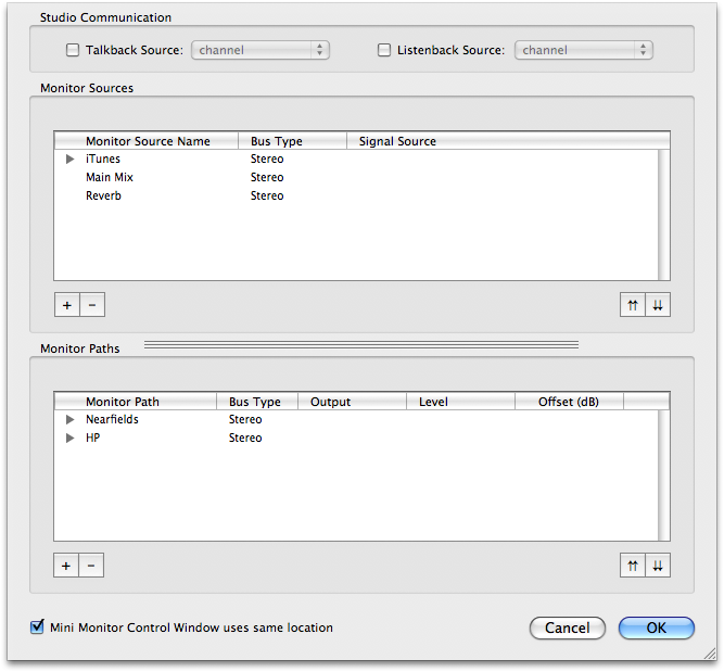
- Click the ‘+’ button in the Monitor Paths section at the bottom of the Configure Monitor Controller sheet. The Add Monitor Output dialog appears.
- Enter the name of the new Monitor Output Path.
- Select the Bus Type of the new Monitor Source.
- Click OK. The new source will appear in the Monitor Source List.
- Click the pop-up menu in the “Signal Source” column for the Left Channel of the source. Select the appropriate physical source channel from the list. This includes Physical Input and DAW channels.
- Repeat step 7 for each of the channels that make up the bus.
- Click Ok. The Monitor Controller now has your Bus Output configured as its Monitor Source, and the Output Path configured above.
Monitor Control Interface and Basic Operation
The Monitor Control window interface has four sections:
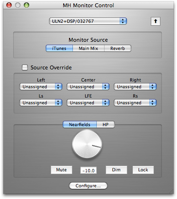
- Global Functions: Includes Moblie I/O selection pop-up menu, Utiliy and Configure buttons
- Monitor Source: Includes tabs to select between defined Monitor Sources
- Source Override: When this box is checked, the sources selected in the Source Override pop-up menu will be routed to the Output Path instead of the selected Monitor Source.
- Output Section: Includes tabs to select between defined Output Paths as well as the monitor controls themselves.
In order to use the Monitor Controller, you’ll need to do the following:
- Configure one or more Monitor Sources
- Configure one or more Monitor Output Paths
- Select a Monitor Source to monitor
- Select an Output Path for your monitored signal
After completing these tasks, you can use the Monitor Control window to control all the monitoring functions for the selected Monitor Source, which you will hear via the selected Output Path.
MIO Console automatically saves your Monitor Sources and Output Paths, so you will only need to define each Monitor Source and Output Path once. You can use the Monitor Controller with only one Monitor Source and one Output Path defined, or you can define as many as you’d like of either or both and use the Monitor Controller to switch between them.
Determine Configuration
The most important step in working with the Monitor controller is to determine how signal is routed through your mixer. Once you know how your signal flows through the mixer to the Mix Bus, configuring and using the Monitor Controller is very simple. In order to configure the Monitor Controller you will need to identify two different types of audio channels in your system:
- Monitor Sources (inputs to the Monitor Controller)
- Monitor Output Paths (outputs from the Monitor Controller)
Identifying Monitor Sources
The selectable input source that you wish to monitor is called the Monitor Source. Your sources can come from the physical hardware inputs of the Mobile I/O or they can be virtual inputs streaming into the MIO over the FireWire cable, and can consist of any number of channels from a mono channel to eight channels forming a 7.1 surround signal. You can freely name your Monitor Source in order to more clearly identify what sources are being monitored. For example, if your monitor source was your AES inputs, you might want to name your Monitor Source “AES input” or simply “AES”. On the other hand, if you have a DAT player connected to your AES input, you might instead want to name the Monitor Source name “DAT”.
You can also use mix busses as sources in the Monitor Controller. To add a mix bus to the Monitor Controller, you simply select the "Add to Monitor Controller" item in the Bus Output pop-up menu at the bottom of the master strip for the bus. This automatically creates a Monitor Controller source for you. The mixer will automatically maintain the routing of the bus output to the monitor controller for you.
When you create a Monitor Source, you specify the type of path you are making, and the name of the new path. The type of path (Mono, Stereo, LCR, LCRS, Quad, 5.0, 5.1, 7.1) you choose will allow the Monitor Controller to automatically create channel slots for each component channel.
The Monitor controller uses the channel assignments to match the sub-channels between Monitor Sources and Monitor Output Paths and automatically route your selected source to your selected Monitor Output Path.
Once you have identified the sources you want to select from in your system, you use the Monitor Controller’s Configuration Dialog to set up the sources. See “Configuring Monitor Sources” for more details.
Identifying Monitor Output Paths
A Monitor Output Path defines a selectable destination for your monitor system. It can be anything from a single Mono channel, to a 7.1 surround path. Monitor Output Paths are associated with real physical outputs that you have connected to Monitoring devices (like Speakers/Amplifiers or Headphones). These destinations are unlikely to change frequently, but you may have more than one destination that you use routinely. For example, you may have the following monitoring systems in your studio:
- Console (or desk) mounted nearfield (small) stereo monitors.
- A larger far-field 5.1 surround monitor system.
- A pair of studio headphones.
You may want to monitor any of the Monitor Sources through any of these monitoring systems, but only through one at a time. So in this case you would configure three Monitor Output Paths, each with its own physical outputs — one for each system listed above.
As with the Monitor Sources, you choose the names for these Monitor Output Paths in a way that makes sense to you.
When you create a Monitor Output Path, you specify the type of path you are making, and the name of the new path. The type of path (Mono, Stereo, LCR, LCRS, Quad, 5.0, 5.1, 7.1) you choose will allow the Monitor Controller to automatically create channel slots for each component channel.
The Monitor controller uses the channel assignments to match the sub-channels between Monitor Sources and Monitor Output Paths and automatically route your selected source to your selected Monitor Output Path
Once you have identified the output paths you want to select from in your system, you use the Monitor Controller’s Configuration Dialog to set up the outputs. See “Configuring Monitor Output Paths” for more details.
Using the Monitor Controller
Using the Monitor Controller is very simple. The Monitor Controller UI only controls one box at a time, so if you have multiple boxes attached you need to select the box you want to control from the pop-up menu at the top of the window.
v.5 Monitor Controller UI
The monitor control window may be set to operate as a “Utility” Window (a “Utility” Window is a floating window that floats above all the other windows in the system — including windows from other applications). When configured in this way, the window will float above all other applications and will always be active (unless hidden). If you click the up-arrow button to the right of the box select popup menu so that it is highlighted, the window will operate as a Utility window. Click the button again (un-highlighting it) to return the window to operation as a normal floating window. The Key Command to hide and show the Monitor Control window is global and may be used to hide and show the Monitor Control window even when you are using other applications. When the Monitor Control window is functioning as a Utility window, it will remain visible and active even when MIO Console is hidden.
Once you have selected the box to control, you only have a few simple tasks to utilize the Monitor Controller.
Selecting an Input Source
The Monitor Source area will contain buttons representing all of your defined Monitor Sources. To select the input that will feed your Output Path, simply click on one of these buttons. The selected input will automatically be routed to the current monitor output. There are key-commands defined for the first eight monitor sources.
Selecting an Output Path
The Monitor Output area will contain buttons representing all of your defined Output Paths. To select the monitor output that will be fed by the selected Monitor Source, simply click on one of these buttons. The selected output will automatically be routed so that it receives signal from the currently selected input. There are key-commands defined for the first eight monitor output paths.
Adjusting the Monitor Level
To adjust the monitor volume, click and drag the Level Control Knob; drag the knob up to raise the volume, drag it down to lower the volume. You can also adjust the monitor level using two-finger trackpad scrolling, mouse-wheel, or mighty-mouse wheel when the cursor is placed over the Level Control Knob. If you know the exact value you wish for the monitor level, you can also click inside the Monitor Level Display and enter a numeric value directly.
Dimming the output
Sometimes, you may want to temporarily drop the output level significantly. For these situations, the Monitor controller includes a Dim button that will drop the output by 20dB when Dim is engaged. Click the Dim button to engage/disengage the Dim function.
Muting the output
Click the Mute button to mute/unmute the currently selected Monitor Output. The button appears grayed out when the output is muted.
Locking the output
Click the lock button to lock/unlock the monitor output level at its current setting. The button appears grayed out when the output level is locked. The Monitor Source and Monitor Output routing capabilities and mute functionality of the Monitor Controller function normally when the output level is locked.
Overriding the currently selected source
By clicking on the Source Override checkbox, you can switch the selected Monitor Source for the sources selected in the channel pop-up menus of the Source Override section. This can be useful if you find that you need to monitor something, or to A/B your normal Monitoring Sources, with a “one off” source. For example, you may have a number of Monitor Sources configured for analog audio streams, audio from your computer, and so on, but for one session only, you may need to monitor a signal streaming in digitally from the AES inputs. So in this situation, rather than configuring a Monitor Source, you might want to simply select the AES inputs in the Source Override channels.
Selecting Source Override Channels
Before you can use the Source Override checkbox, you need to use the channel pop-up menu to select a source for at least one channel.
You do not need to select sources for every pop-up menu in the Source Override section:
- For Mono signals, select a source for the Left channel.
- For Stereo signals, select sources for the Left and Right channels.
- For Quad signals, select sources for the Left, Right, Ls, and Rs channels.
The Monitor Controller as Floating Window
You can configure the Monitor Controller to be a floating window, also known as a “Utility Window” in official Mac OS X terminology. As a Mac OS X Utility Window, the Monitor Controller will remain “floating” on top of all other windows on screen, even if the MIO Console application is hidden. One advantage to setting the Monitor Controller to be a floating window is that you will always be able to quickly adjust the monitoring level regardless of how many other windows you have active. If you have an unexpected noise burst, this feature might just save your equipment—and your hearing!
Click the Up Arrow button in the upper right corner of the Monitor Control window to toggle between Utility and non-Utility mode.
Mini Monitor Controller Window
The full Monitor Control window requires a fair amount of screen space. For this reason, you can invoke a Mini Monitor Controller window, which offers nearly identical functionality in a window much smaller than the full Monitor Control window.
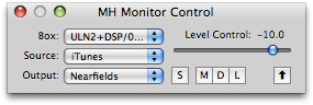
v.5 Mini Monitor Controller UI
As you can see, the Mini Monitor Controller offers identical buttons for Dim, Mute, and Lock, as well as the Utility Window button in the upper right corner. You can select among your configured Monitor Sources and Output Paths using the respective pop-up menus. You can invoke the Source Override section using the “S” button. You can adjust the volume level using the Level Control slider. Invoking the Configure window and choosing Source Override channels are the only functions that you cannot do from the Mini Controller window.
Switch between Monitor Controller and Mini Monitor Controller windows
You can toggle the display between the large Monitor Control Window and the Mini Monitor control window by clicking the Zoom button in the window’s title bar (the little green + pill).
Note: Here’s a way to conserve screen space while keeping the Monitor Controller available:
- Configure all your Monitor Sources, Output Paths, and Source Override channels in the Monitor Control window
- Toggle the window to the Mini Controller
- Click the Utility mode button
- Place the Mini Controller in an unobtrusive part of your monitor, such as one of the corners.
Key Commands
The Monitor Controller defines key commands for each of its operations. You can change the default key commands with the Console’s Key Commands window. If you have a programmable HID device (like the Contour Shuttle Pro), you can assign appropriate key-commands to the buttons of the HID device to control the monitor controller. You can edit all the Key Commands in MIO Console.
The following table lists all the default key commands:
Default Monitor Control Key Commands
| Command | Key Sequence |
| Switch to/from Mini Controller | ⌘⌥⌃F (Command + Option + Control + F) |
| Volume Up | ⌘⌥⌃↑ (Command + Option + Control + up arrow) |
| Volume Down | ⌘⌥⌃↓ (Command + Option + Control + down arrow) |
| Toggle Dim | ⌘⌥⌃D (Command + Option + Control + D) |
| Toggle Mute | ⌘⌥⌃M (Command + Option + Control + M) |
| Toggle Window Visibility | ⌘⌥⌃V (Command + Option + Control + V) |
| Select Monitor Source 1 | ⌘⌥⌃1 (Command + Option + Control + 1) |
| Select Monitor Source 2 | ⌘⌥⌃2 (Command + Option + Control + 2) |
| Select Monitor Source 3 | ⌘⌥⌃3 (Command + Option + Control + 3) |
| Select Monitor Source 4 | ⌘⌥⌃4 (Command + Option + Control + 4) |
| Select Monitor Source 5 | ⌘⌥⌃5 (Command + Option + Control + 5) |
| Select Monitor Source 6 | ⌘⌥⌃6 (Command + Option + Control + 6) |
| Select Monitor Source 7 | ⌘⌥⌃7 (Command + Option + Control + 7) |
| Select Monitor Source 8 | ⌘⌥⌃8 (Command + Option + Control + 8) |
| Select Monitor Output 1 | ⌘⌥1 (Command + Option + 1) |
| Select Monitor Output 2 | ⌘⌥2 (Command + Option + 2) |
| Select Monitor Output 3 | ⌘⌥3 (Command + Option + 3) |
| Select Monitor Output 4 | ⌘⌥4 (Command + Option + 4) |
| Select Monitor Output 5 | ⌘⌥5 (Command + Option + 5) |
| Select Monitor Output 6 | ⌘⌥6 (Command + Option + 6) |
| Select Monitor Output 7 | ⌘⌥7 (Command + Option + 7) |
| Select Monitor Output 8 | ⌘⌥8 (Command + Option + 8) |
Configuring the Monitor Controller
Click the “Configure…” button to open the Configuration Dialog for the Monitor Controller. See the next sections for details.
Configuring Monitor Sources
To access the Configuration Dialog, click the “Configure…” button in the Monitor Controller window:

The Monitor Controller’s Configuration Dialog sheet will open:
To Add a New Monitor Source:
- Click the ‘+’ button in the Monitor Sources pane.
- The Add Monitor source dialog appears:
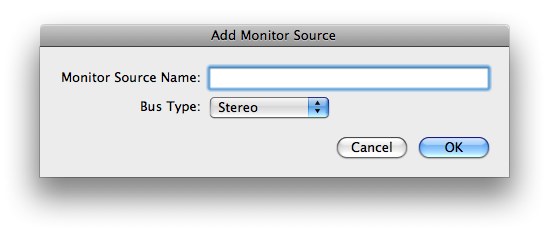
- Enter the name of the new Monitor Source.
- Select the Bus Type of the new Monitor Source.
- Click OK. The new source will appear in the Monitor Source List:
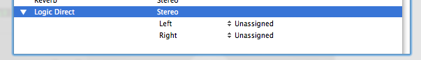
- Click the pop-up menu in the “Signal Source” column for the Left Channel of the source. Select the appropriate physical source channel from the list. This includes Physical Input and DAW channels.
- Repeat step 5 for each of the channels that make up the bus.
- If you decide (now or later) that you want to change the name of the Monitor Source, you can edit the name in the list (you can double-click the name to edit it).
- Repeat from step #1 for each source you want to add.
To Remove a Monitor Source:
- Click the source(s) you want to remove in the Monitor Source List.
- Click the ‘-‘ button.
To change the order of the Monitor Sources:
- Click the source(s) you want to move in the Monitor Source List.
- Click the up-arrow button to move the selected sources higher in the list.
- Click the down-arrow button to move the selected sources lower in the list.
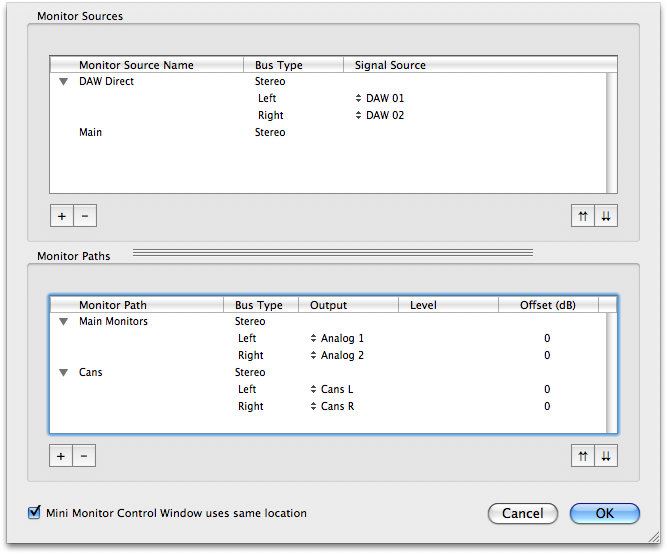
Configuring Monitor Output Paths
Monitor Output paths are more configurable than Monitor sources; besides configuring the actual output channels in the path, you can also define the level standard used by the output channel (if your hardware supports that) and per-channel level offsets. This is useful for compensating for gain structure differences in output paths on a per-channel basis. For example, if you have some balanced amps and unbalanced amps in your system you can define different level standards for them, or if different amps have different sensitivities, you can define different per-channel offsets. The per-channel level control and per-channel output type controls are accessed from the Monitor Controller configuration dialog.
The Monitor Controller also supports per-path level calibration to allow you to calibrate and normalize levels between different output paths. This can be used to set your nominal 0 dB level to match a monitoring standard or to normalize levels between multiple monitor paths.
To access the Configuration Dialog, click the “Configure…” button in the Monitor Controller window:
The Monitor Controller’s Configuration Dialog sheet will open:
To Add a New Monitor Output Path:
- Click the ‘+’ button in the Monitor Paths pane.
- The Add Monitor Output dialog appears:
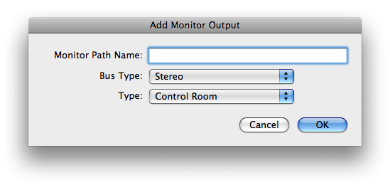
- Enter the name of the new Monitor Output Path.
- Select the Bus Type of the new Monitor Source.
- Don't worry about the “Type” pop-up menu — it is reserved for future use. All you need to know is that the Type must be “Control Room” for the Monitor Controller to work correctly.
- Click OK. The new source will appear in the Monitor Paths List:
- Click the pop-up menu in the “Output” column for the Left Channel of the Monitor Path. Select the appropriate physical destination channel from the list.
- Repeat step 7 for each of the channels that make up the bus.
- If you decide (now or later) that you want to change the name of the Monitor Output Path, you can edit the name in the list. Double-click the name to edit it.
- Repeat from step #1 for each Monitor Output Path you want to add.
![]()
To Remove a Monitor Output Path:
- Click the output path(s) you want to remove in the Monitor Paths List.
- Click the ‘-‘ button.
To change the order of the Monitor Output Path:
- Click the output path(s) you want to move in the Monitor Paths List.
- Click the up-arrows button to move the selected output paths higher in the list.
- Click the down-arrows button to move the output paths lower in the list.
To change the per path Calibration:
The Monitor Output Path calibration control is accessed via a contextual popup menu on the main Monitor Controller level control knob: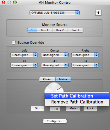
v.5 Monitor Control Calibration
To Calibrate a Monitor path:
- Select the output path to calibrate (Mains in the screenshot above).
- Adjust the level knob to generate the desired reference level at the output.
- <control>-click (or right-click a multi-button mouse or trackball) the knob to popup a contextual menu.
- Select the Set Path Calibration item.
- The calibration will be set for the path, and the level control will be adjusted to read 0.0.
To Remove Calibration from a Monitor path:
- Select the output path to calibrate (Mains in the screenshot above).
- <control>-click the knob to popup a contextual menu.
- Select the Remove Path Calibration item.
- The calibration will be removed from the path, and the level control will be adjusted so that the output level does not change.
Monitor Controller FAQ:
- Why are some of my output trim controls greyed out in the “Analog I/O Control” pane of the MIO Console window?
A: When you have assigned an output as part of a Monitor Path, the monitor controller takes control of that channel for the purpose of controlling its output level. Since the monitor controller is controlling the channel level, it would not make sense for the trim knob in the Analog I/O Control pane to also change that setting. As a result, the corresponding control in the “Analog I/O Control” pane is disabled and its setting automatically updated as you adjust the Monitor Controller. If you remove that channel from all Output Paths in the monitor controller, that output will be restored to manual control in the “Analog I/O Control” pane, and its trim knob will no longer be greyed out.
- Why are some of my output routing controls greyed out in the Output Patchbay of the “Mix/Output Routing” pane of the MIO Console window?
A: When you have assigned an output as part of a Monitor Path, the monitor controller takes control of that channel for the purpose of controlling its routing. Since the monitor controller is controlling the channel, it would not make sense for you to change the routing independently. As a result the corresponding routing control in the “Mix/Output Routing” pane is disabled and “greyed out”. Its setting is automatically updated by the monitor controller as you make changes, and if you remove that channel from all monitor paths, it will be restored to manual control in the “Mix/Output Routing” pane.
- Why is the Monitor Level Control and Dim button greyed out and disabled?
A: There are two reasons that the Level Control can be disabled. The first reason is that you have locked the Level Control with the “Lock” button. The second reason is that there is no currently selected Output Path. - Why does selecting one Monitor Path mute all the other Monitor Paths?
A: Control Room Monitor Paths are exclusive; only one is active at a time. As a result, selecting one Monitor Path will automatically mute all the other paths. If you want an output to be active all the time, route it manually in the patchbay — don’t add it to the Monitor Controller. This would be appropriate for an aux send, for example. - I can’t figure out how to configure the Monitor Sources or Output Paths from the mini Monitor Control Window. How do I do it?
A: You can’t configure the Monitor Controller directly from the mini Monitor Control Window. You need to switch back to the large Monitor Control Window first by clicking the Zoom button in the mini Monitor Control Window. - I can’t figure out how to configure the Source Override sources from the mini Monitor Control Window. How do I do it?
A: You can’t configure the Source Override directly from the mini Monitor Control Window. You need to switch back to the large Monitor Control Window first by clicking the Zoom button in the mini Monitor Control Window.