Using the ULN-8 Hardware
ULN-8 Front Panel
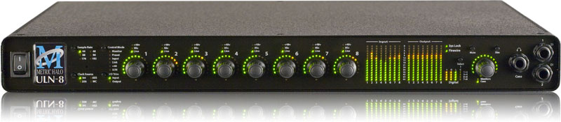
The front panel provides ULN-8 system control and status at a glance:
- Power switch for rear 4 pin XLR connector (jumper defeatable)
- Sample Rate (nominal 44.1, 48, 88.2, 96, 176.4 or 192KHz)
- The Sample Rate is determined from the currently selected clock source so it will accurately indicate the current sample rate, even when the clock source is being provided by an external device.
- Clock source:
- Internal indicates that the system is internally clocked
- Wordclock indicates that system is being clocked from the wordclock input
- 256x WC indicates that the system is being clocked from a 256x clock at the wordclock input
- Digital In indicates that the system is being clocked from the selected digital input
- Control Mode — Indicates what parameters the encoders are modifying:
- Monitor- Select the Monitor Controller input or output
- Preset- Recall one of the eight stored system configurations
- Input- Step through the available input sources
- Link- Link multiple input and output encoders for stereo or multichannel use
- +48- Enable phantom power, per channel
- U/M- User mode (for future expansion)
- I/O Trim — Indicates whether you are modifying input or output channel gain.
- Input Status- Indicates mic input, line input or mic s/r by channel.
- Encoders- Eight detented encoders for multipurpose control, with push-switches.
- 15-segment metering for the 8 analog inputs and outputs using multicolor LEDs, which also display gain values during encoder use. The meters are fast PPM peak reading meters with auto-resetting peak holds.
- SysLock — Indicates that the system clock recovery circuit is properly locked to the selected clock source. If this light is not illuminated, the ULN-8 will not be locked to a clock and will revert to its failsafe internal clock source. Even if the Locked light is not illuminated, the actual sample rate will still be indicated on the front panel display.
- FireWire — Indicates that the ULN-8 has been successfully connected to a FireWire bus and has detected the isochronous cycle required to transmit and receive audio.
- Signal present indicators for AES input and output, as well as digital lock and cable select button and indicators.
- Monitor Control Section:
- The Mute and Dim buttons provide instant access to simple level control for the selected Monitor path or headphone output. The Mute button provides a quick, tactile “panic switch” which mutes the monitors or front panel headphone output in case of accidental feedback loops and other audio unpleasantries. The Dim button attenuates the selected path by 20 dB.
- The Monitor Control encoder provides front panel adjustment for your audio. By pressing the encoder, it can toggle between affecting the Monitor Control section or headphones. There are two multicolor LEDs below the encoder that indicate which path the encoder is modifying as well as mute and dim status.
The ULN-8 front panel also provides access to the Headphone output. The headphone output jack is a TRS 1/4” jack that provides the Left Channel on the tip, the Right Channel on the ring and the ground return for the two channels on the sleeve. These signals are all ground referred, so they may also be split and fed single-ended (unbalanced) to an external audio device.
There are two DI inputs on the front panel, which are paralleled with Line inputs 1&2. The DI inputs can provide 0, 10, or 20db of gain selectable via internal jumpers.
More information regarding the front panel can be found here.ULN-8 Rear Panel
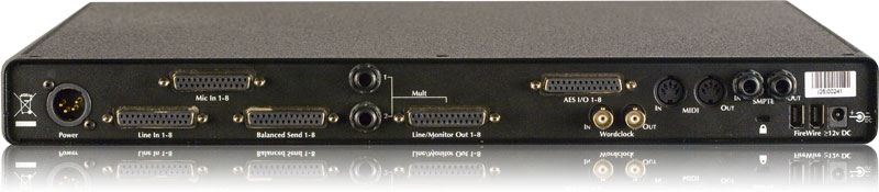
- 4 pin XLR DC power jack (14v - 28v, 32 Watts)
-
8 channels balanced mic inputs on DB25. Each input has:
- -22 dB to +91.5 dB of gain range
- Dynamic Range (-60 dB, flat 0-22.05 kHz, typ): 115 dB
- +0/-1.0dB @ fs = 192KHz: 2.9 Hz - 64.7 kHz
- Noise Floor (flat 0-22.05 kHz, typ): 115 dB
- remote switchable 48v Phantom power, with 10mA current limit
-
8 channels balanced line inputs on DB25. Each input has:
- -12 dB to +31.5 dB of gain range
- Dynamic Range (-60 dB, flat 0-22.05 kHz, typ): 115 dB
- +0/-1.0dB @ fs = 192KHz: 1.8 Hz - 64.7 kHz
- Noise Floor (flat 0-22.05 kHz, typ): 115 dB
- 8 channels balanced line level sends on DB25 that mirror the selected input
-
8 channels balanced line/monitor outputs on DB25. Each output has:
- 24-bit 192kHz D/A converters (120dB SNR)
- Gain range from -96 dB to +30 dB
- Outputs 1&2 also multed to 1/4" TRS connectors
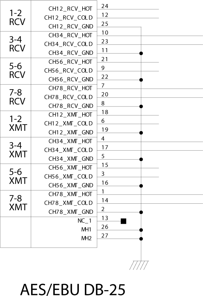
- 8 channels AES digital I/O on DB25
- Single wire mode for full 8 channels at 44.1-192KHz operation
- Wordclock input/output on BNC connectors at 1x or 256x rates
- MIDI I/O to connect a control surface to MIO Console
- SMPTE input and output on 1/4" TRS
- Kensington security slot
- 2 IEEE 1394 (FireWire) ports (400 Mbs)
- 1 2.1mm DC power jack (14v - 28v, center positive, 32 Watts), unswitched
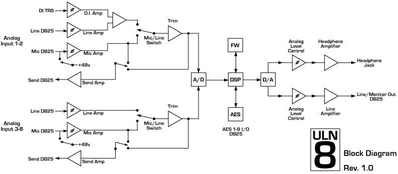
Signal Flow
Making connections to the ULN-8
There are seven classes of connections you can make to the ULN-8 hardware:
- Analog Audio
- AES Digital Audio
- Clock Sync
- FireWire
- Power
- MIDI
- SMPTE
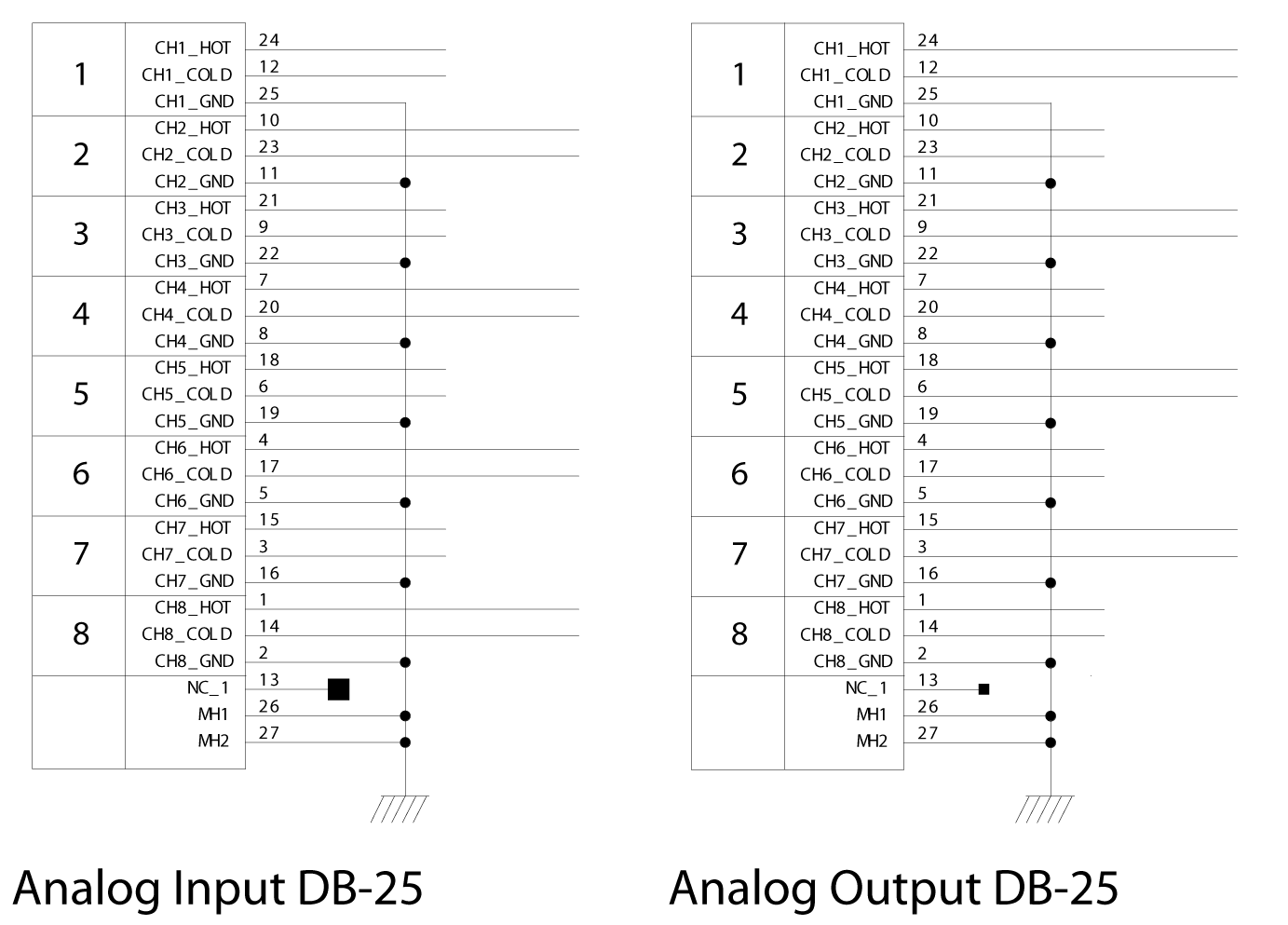
ANALOG AUDIO CONNECTIONS
The analog I/O connections on the ULN-8 have been engineered for maximum flexibility in that they support both balanced and unbalanced connections with a wide range of input and output levels and a wide range of matching impedances. The microphone inputs have an impedance of 3.3 kΩ, and the line inputs are 10 kΩ. With that in mind, there are a number of aspects of the design that you should take into account when interfacing with the ULN-8. All multichannel audio connections are made using industry standard DB25 connectors, which are pin- compatible with cables using the Tascam/Digidesign standard.
Whenever possible, use balanced connections with the ULN-8. The performance of balanced interconnects is much higher and much more resistant to noise interference and electrical (power) wiring problems. The expense of balanced interconnects is not substantially higher than unbalanced connections, so if the gear that you are interfacing with supports balanced connection — use it. If you cannot utilize balanced interconnects, there are connection schemes that you can use that will maximize performance.
On input, at line level, it is sufficient to simply use standard unbalanced (TS) connections. If you are interfacing with the Mobile I/O XLR inputs, you will need to ensure that pin 3 is grounded in the unbalanced adapter cable. More information about adjusting the input level can be found in the MIO Console software chapter.
ULN-8 DB25 cables should be wired pin 2 or Tip hot. The front and rear 1/4” connectors are wired Tip hot. The headphone connector is wired Tip/Left, Ring/Right, Sleeve/Ground.
Connecting to the DIs
The DI inputs provide an excellent high impedance input for directly connecting instruments to the ULN-8. These inputs are unity-gain summed with the corresponding line input from the back panel. This means that if you have signal connected to both the DI and line input for a given channel the ADC will see a mix of those two inputs. If you do not wish to have signal from one of the connectors you need to physically disconnect that input or otherwise ensure that no signal is present at the unused input.
You may notice that the MIO Console has an input selection for "Inst". This can be used as a visual reminder that you are plugged into the DI, but has no operational effect on the input. Selecting "Inst" on any channel of the ULN-8 sets the input to Line +4; the only DI input is available from the front panel jacks for inputs 1&2.
Each DI input supports balanced connections via TRS cable. You can connect a source to the DI via a balanced interconnect (if the source is actually a balanced output), an unbalanced interconnect (if the source is unbalanced like most instruments), or a telescoping shielded cable (which is an alternate unbalanced connection that provides additional shielding).
Since the DI inputs provide an ultra-high input impedance, if you connect an unbalanced source to the DI via a balanced cable you will float the negative input and will effectively inject a large DC offset into the output of the DI which will cause the associated ADC to mute. As a result you must use either a TS cable or a telescoping shield cable with unbalanced sources.
When you remove the connector from the DI jack, the DI connects its inputs to ground internally to remove any possible residual DC offset or pickup noise. If you disconnect the cable from the source but leave it connected to the DI input, the cable will function as an antenna and will inject noise into your inputs and may cause enough of a DC offset to mute the ADC. As a result you should always disconnect the cable from the DI rather than the instrument.
Balanced Sends and Mic S/R Mode
The ULN-8 has eight balanced sends; these mirror the analog input you have selected to feed that channel's A/D convertor. For example, if you select the Mic input on analog channel 1, the output of that mic preamp will be available at send 1. If you select the Line input on analog channel 1, the Line in signal will be available at send 1. This allows you to use the sends as a splitter to feed a mixing console, recorder or other equipment.The "Mic S/R" input mode creates pre-convertor inserts on a per-channel basis by utilizing the Mic input as the channel input and Line input as the insert return. For example, to insert a compressor on Analog 1:
- Set Analog 1's input type to Mic S/R
- Connect your signal (mic or line level) to Mic input 1
- Connect Send 1 to your compressor's input
- Connect your compressor's output to Line input 1
AES DIGITAL AUDIO
The ULN-8 supports 8 channels of digital audio over copper-based connections. The native format of the ULN-8 is AES, but can be converted to SPDIF or optical using third-party adapters. The ULN-8 operates in single-wire mode, providing 8 channels of digital audio at all sample rates. The ULN-8's digital I/O connections are made using industry standard Tascam/Digidesign pinout DB25 cables. If you want to connect the ULN-8 to a device that uses the Yamaha DB25 pinout, you will need to source a DB25 crossover cable.
CLOCK SYNC
Clock sync is a serious consideration in any digital audio system.
If you are recording analog sources with ULN-8, you can simply use the unit’s high-quality internal clock source to drive the converters. This is the easiest case to deal with.
If you need to interface with other devices digitally or ensure sample accurate sync with video sources, the extensive clock synchronization capabilities of ULN-8 will prove to be more reliable (and better sounding) than most higher priced alternatives.
There are three different ways to get external clock information into the unit:
- Sending a 1x word clock signal into the WC Input BNC.
- Sending a 256x word clock signal into the WC Input BNC.
- Sending an AES signal into the Digital input.
The BNC word clock input port is a 75 Ohm terminated coaxial input. It should be driven by a 75 Ohm source driver and interconnected with 75 Ohm coaxial cable. If you do not use proper cabling and source drive, you will introduce reflections on the word clock cable which will propagate jitter into the recovered word clock. This is true whether you use the port as a 1x WC input or a 256x WC input, but becomes more important when the clock signal is 256x.
1x is generally appropriate for use with devices that provide a word clock output. If your device provides a 256x output, you may find that you get better results using that clock signal. The Digidesign® line of Pro Tools® products use 256x as their “ SuperClock™” clocking signal.
The AES recommended procedure for distributing clock is to use an AES clock signal. The AES clock signal is an AES digital audio signal with no audio activity. The ULN-8 only uses the AES preambles for clock recovery, so it is immune to data dependent jitter effects. This means you can reliably use the Digital Input as a clock source with or without audio data.
FIREWIRE
FireWire® is Apple’s registered trademark for the IEEE 1394 High-Speed Serial Bus. FireWire started as an Apple technology to replace a variety of interface ports on the back of the computer. After promulgating a number of closed proprietary technologies in the early days of the Macintosh, Apple determined that open standards were better for the Mac, for the industry, and for Apple itself. On that basis they opened their technology for standardization under the auspices of the Institute of Electrical and Electronics Engineers, Inc. (IEEE), an international organization that promotes standards in the field of electronics. FireWire was standardized as IEEE 1394 and promoted for open licensing in the industry.
The first widespread adoption of the technology was for DV camcorders where space was at a premium and bus powering was not perceived as a real issue since all camcorders have batteries. Sony designed an alternative version of the standard 6-pin FireWire connector that provided 1394-based communication with 4-pins in a much smaller form-factor. This version of the connector sacrificed bus-power support and mechanical stability for reduced space requirements. Sony dubbed this version of IEEE 1394 “i.Link®.” This became the de facto standard in the DV world, and was later added to the IEEE 1394 standard. Both i.Link and FireWire refer to the same underlying standard and are completely interoperable. Obviously, i.Link connectors and FireWire connectors cannot be used together without adapters.
The ULN-8 uses the FireWire flavor of the IEEE1394 connector with 6-pins. The unit ships with two 6-pin to 6-pin FireWire cables, one that is 0.5 meters long (about 18 inches), and the other 4.5m (about 14.5 feet) long. If you want to use the ULN-8 with a 4-pin FireWire device, you will need to purchase a 6-pin to 4-pin adapter cable. These cables are available from a wide variety of retail sources.
The 6-pin FireWire connector is polarized by its shape, one end of the connector is pointed. The FireWire ports on the ULN-8 point downwards toward the bottom of the box. It will be very difficult to insert the connector upside down, but it is possible if you force it. If the plug is inserted into the socket upside down, the socket will be destroyed. NEVER FORCE A FIREWIRE CONNECTOR INTO A FIREWIRE SOCKET.
Devices connected to the FireWire bus are autoconfiguring. You do not need to set IDs or DIP switches or in any way configure the devices in order to facilitate communication between devices or to configure the bus.
FireWire devices on the same bus must be connected in a tree structure with no loops. This means that devices can be connected to each other in any order, and any device with multiple ports can act as a chain or a hub for other FireWire devices, but you should never be able to get from one device to another by more than one path. If you construct a loop in the bus, it will not operate properly and you will not be able access some or all of the devices on the bus.
Although you are able to attach devices in any order on the FireWire bus, the order of attachment will have an impact on performance. Most current model FireWire devices support 400 Mbs operation, but many older devices may only support 100 or 200 Mbs operation. These devices act as a bottleneck in the bus and limit the speed of any bus traffic that flows through them. In order to maximize performance, you want to ensure that low speed devices are not used to join high speed devices. In practice this generally means that you should attach your ULN-8 directly to your computer or through a high speed hub.
To connect the ULN-8 to your computer simply plug a FireWire cable into the ULN-8 and into the computer. The FireWire bus provides a path for all communication between the computer and ULN-8 – audio, control and meter data.
ULN-8 audio transport takes advantage of FireWire’s support for isochronous transmission, in which the ULN-8 can reserve a dedicated amount of bandwidth on the bus for moving audio samples. Since the audio must be transmitted on a regular basis to ensure continuous playback and recording , the isochronous model is perfect.
Control changes and meter data are transmitted using asynchronous transactions on the FireWire bus. This transmission approach makes use of the unreserved bandwidth on the bus and competes with things like FireWire hard disk accesses for time. Under normal circumstances this is completely transparent to the user. If the bus becomes overloaded, you may find that disk accesses and meter updates slow down. If you are experiencing bus overloads, you can always add a second FireWire bus with a third-party FireWire card (PC-Card, ExpressCard or PCI card depending on your machine), and offload one or more devices to the second bus.
POWER
One of ULN-8’s great strengths is the flexibility of its power system. The ULN-8 can be powered from any DC source in the range of 14V to 28V as long as it provides 32 Watts of power. The DC inputs on the ULN-8 are a 2.1mm coaxial power connector, center positive and a 4-pin XLR connector Pin 4 Hot. So if you are powering the unit with a third party power source and it supplies 14V, the power source will have to provide 2.3 amps of current. If you are powering the unit with 24V, the power source will have to provide 1.3 amps of current, and so on.
The ULN-8 ships with a world-ready 24 volt, 2 amp power supply. You can plug this supply into any AC power source from 90V to 240V, 50Hz - 60Hz, using an appropriate IEC power cord, and it will supply the proper power to the ULN-8 on the 4 pin XLR power connector. The ULN-8 will not supply power to the FireWire bus, but will pass power coming from other devices.
As with all electronic devices, when connecting an external power source to the ULN-8, you should first connect the power source to the ULN-8 while it is in an unenergized state (e.g. not connected to the mains or switched off). After the connection to the ULN-8 has been made, you should energize the power source.
If you connect an energized power source to the ULN-8’s 2.1mm power connector you may see a small spark when you make the connection. This is due to surge current and is normal if you connect a power source in this way. While this will not damage the ULN-8 in any way, to avoid the spark just connect the power connector to ULN-8 before connecting the power source to the wall.
MIDI
The ULN-8 offers MIDI input and output ports for direct connection of a control surface. These ports are only active while MIO Console is running; the ULN-8 cannot utilize a control surface in standalone operation. MIO Console makes these ports available to other applications while it is running, but the MIDI implementation is currently optimized for control use only- it is not recommended to use these ports for connecting keyboards or other devices that require accurate timing.
SMPTE
The ULN-8 has SMPTE input and output ports for timecode use. The SMPTE input occupies its own channel and does not require using a channel of A/D conversion. SMPTE is presented to CoreAudio applications as channel 19 in our driver. It is accessable via any CoreAudio compliant software, including the Record Panel in MIO Console.
More information regarding the ULN-8 can be found in these documents:ULN-8 Overview
Front Panel Guide