+DSP Implementation Guide
Plugin Processing in Legacy +DSP
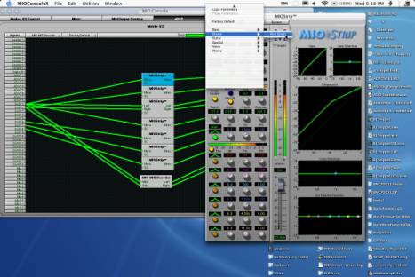
The +DSP Panel is the heart of the plug-in system in Mobile I/O:
The +DSP Panel includes a number of elements. The large dark area with the grid is the "Graph area". To the left of the Graph area are the input ports from the primary DSP (the DSP that provides the mixing, metering and routing services on Mobile I/O). On the right are the output process bus ports that return the processed signal to the primary DSP. Along the top of the Graph area are a number of controls that you use to configure the DSP signal processing. Right next to the "Inputs" label is the Plug-in pop-up menu. Next to that is the Patch library popup menu. The header then has a spacer, followed by a DSP load meter. Next to the DSP load meter is a DSP popup menu. These are all described below.
DSP pop-up menu
We'll start with the DSP pop-up menu. This lists the available DSP's in the system. There should be one for each +DSP box you have attached to your computer. They will be listed by box type, serial number, and DSP number. All the +DSP units have one available DSP (DSP #1). The software is capable of addressing any number of boxes, so if you have more than one MIO, you can work with multiple DSP graphs.
Plug-in pop-up menu
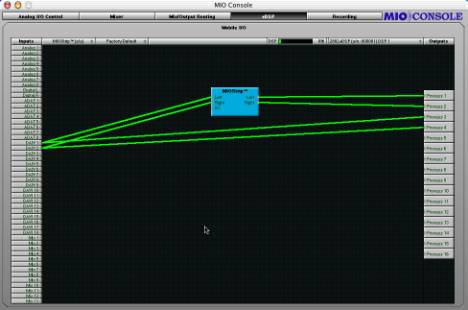
The Plug-in pop-up menu contains all of the available instantiable plug-ins. When you select a plug-in from this menu, a new instance is created on the selected DSP, and you may drag the instance to a convenient location in the Graph area.
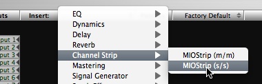
Selecting a new instance from the Plug-in Menu
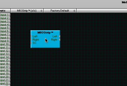
Positioning the new instance in the Graph
Once you have added the Plug-ins you want to use, you can wire them up. To make connections, click on a port (one of the small gray triangles next to the port name), and then drag the connection to the target. When you have made a valid connection, the connection line will switch from Gray to Green. You can make as many mults as you like of a signal source but only one connection can be made to a processor input or process bus port. If you make a new connection to an input that already has a connection, the old connection will be automatically disconnected. To remove a connection without establishing a new one, <control>-click on the input port to which the connection is made.
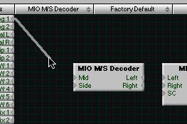
Starting a connection
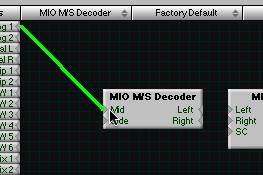
Completing the connection
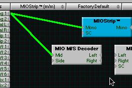
Making a mult
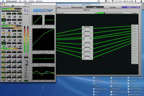
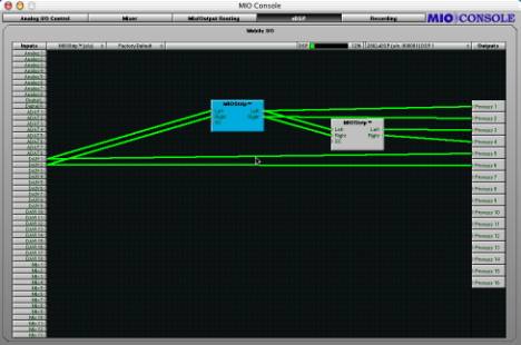
After everything is placed and wired up, you will need to ensure that you have routed the output of your signal processors to the appropriate process bus on the output side of the graph. When you are done, you will have a complete graph. For example:
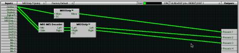
A complete +DSP Graph
This graph shows the routing of Analog 1+2 into a M/S Decoder, and mults Analog 1 to a Mono MIOStrip. The output of the M/S Decoder is routed into the inputs of a Stereo MIOStrip. The outputs of the MIOStrips are sent to Process Busses 1, 2, and 3. It is important to connect both the input and output of a plug-in if you want to use it. The +DSP system is very intelligent about scheduling resources, and will only run plug-ins when they have at least one input and one output connected.
The graph is continuously modifiable. You can drag the plug-ins around as you like, and you can add new plug-ins, even while you are processing audio with the existing graph. You can make and break connections as you please.
There is no routing delay within the plug-in graph. So if you make mults with different plug-in paths on each side of the mult, the two paths will remain time-aligned. This allows you to configure parallel processing paths without the virtually impossible task of time-aligning the parallel paths. The graph itself has a 16 sample delay from input to output, so signals routed through the graph get back to the primary DSP 16 samples after they leave it.
At this point, you will want to be able to control each plug-in's parameters. We will describe the Plug-in UI's below, but, in order to open a plug-in's UI, all you have to do is double click the plug-in in the graph.
Patch Library Pop-up Menu
The Patch Library pop-up menu allows you to save the complete state of the plug-in graph. This menu works like all the other Library popup menus in MIOConsole.
DSP Load Meter
The DSP Load Meter shows you the current active, measured load on the DSP that is selected in the DSP pop-up menu. Since the plug-ins in Mobile I/O are dynamic, this is the best way to determine if you are close to overloading the DSP. The Plug-ins in Mobile I/O only use the resources they need to accomplish the job that you have selected with the plug-in settings. So, if the compressor in MIOStrip is not enabled, it will not use up DSP cycles. This means that you can instantiate more plug-ins if you do not use all the features of each instance. The Load Meter shows you the actual dynamic load, and will vary with the settings of the plug-ins and may vary with the audio program material (depending on the DSP algorithm; e.g. the compressor uses more DSP when the signal is above threshold than when it is below threshold).
Plug-in UI's
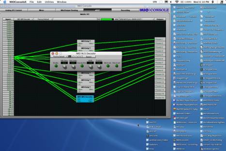
To open the UI for a plug-in, double click the plug-in in the graph.
The M/S processor uses a generic interface -- one that is automatically created from the parameters in the plug-in. The MIOStrip uses a custom interface -- one generated by us with a specific layout and special UI elements. All of the plug-in UI's share the plug-in bar at the top of the window. This bar provides generic services for managing the state of any plug-in.
![]()
Every plug-in window has a parameter library popup, 5 setup registers and a master bypass button. The parameter library popup is like all the other parameter library popups in the console. The parameter library is automatically shared amongst all instances of a particular plug-in type. Actually, it is automatically shared amongst all instances of compatible plug-in types, so MIOStrip Mono and MIOStrip Stereo automatically share preset libraries.
The 5 setup registers are a unique feature of +DSP. Each button corresponds to a set of parameters. If the button has not been activated, the register will be clear, and nothing will happen when you click on the button. When you click onto another register button, the current plug-in parameters will be saved into the register button. This allows you to make multiple alternate setups, and instantly switch between the setups. Sort of an A/B/C/D/E switch.
Finally, the bypass button in the header bar is a master bypass for all processing in the plug-in.
The processing in MIOStrip is a completely new set of algorithms. While we worked to stay within the original spirit of ChannelStrip, the algorithms are radically different. We believe that you are really going to enjoy the sounds you can get out of these processors. The Compressor, especially, is a dramatically different beast. While you can still get the kinds of sounds that you could from ChannelStrip (for those of you who loved that aspect of ChannelStrip), you can get many new sounds that ChannelStrip could not create, and, in particular, you will find that it behaves like a standard compressor in its controls and behaviors, unlike ChannelStrip (for those of you who hated that aspect of ChannelStrip).
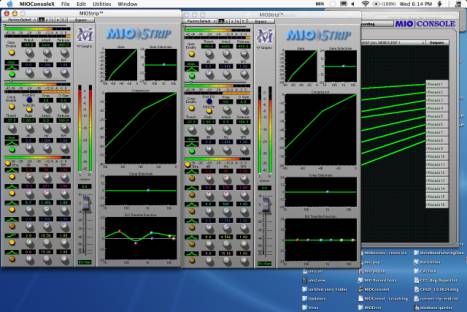
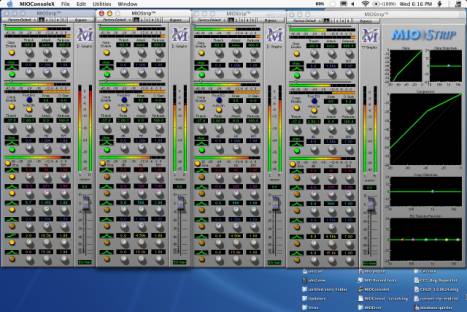
Finally, here is a gallery of configurations: