MIO Console Overview For Legacy Devices
MIO Console
MIO Console is the nerve center of your Mobile I/O. Functioning as a standalone application, MIO Console provides full control of every aspect of Mobile I/O. The console software allows you to rapidly and easily adjust all of the Analog Input and Output channel parameters, system sample rate, Digital I/O source, and system clock source. It also allows you to assign CoreAudio output channels and hardware input channels to the integrated 80-bit, fully-interpolated, multi-bus, near zero-latency hardware mixer.
All new Metric Halo interfaces come with a 2d card and are called 2d Expanded; you can also add the 2d card to older units. If you are using a 2d Expanded unit, you should consult the MIO Console Overview For 2d file for details on using the v5 Mixer. This document details using MIO Console with interfaces with no 2d card, which we refer to as "Legacy" boxes. If you are using a Legacy box, you must go to the MIO Console preferences and enable "Legacy Box Support". All features discussed from this point forward are for Legacy boxes running on v.5 of MIO Console or greater.
On Legacy units, MIO Console’s powerful mixer supports both mono and stereo busses, with solo and mute functions for all input and master channels. The mixer bus outputs are routable to any of the hardware outputs, allowing you to easily create multiple simultaneous mixes for send/return busses and multiple live main and monitor mixes. Applications for these features include: foldback support for multiple performers, separate monitor feeds for studio, tape, and control room, and separate mixes for front of house, archive recording, and monitors for live shows.
MIO Console also contains a patchbay router, which allows you to quickly select the source being fed to any output. The patchbay provides easy configuration of stand-alone operation, mix mults, direct outs and various combinations thereof to suit the needs of the moment.
In order to simplify work flow and optimize the extent of system control, MIO Console supports comprehensive preset management on both a global and individual control level.
The preset management popup controls within MIO Console allow you to configure various aspects of Mobile I/O and save that configuration information for later recall. Various applications include storing routing configurations for monitor setups, mixer configurations for stem and scene recall, and storing analog level standards for interfacing with external gear and managing different mastering standards.
Global configuration snapshots allow you to save each and every aspect of Mobile I/O's configuration for later, total instant recall. This is useful for preconfiguring Mobile I/O and bringing back the configuration once at the gig, managing separate location setups, or for saving complex studio routing setups for quick changeover.
MIO Console Overview
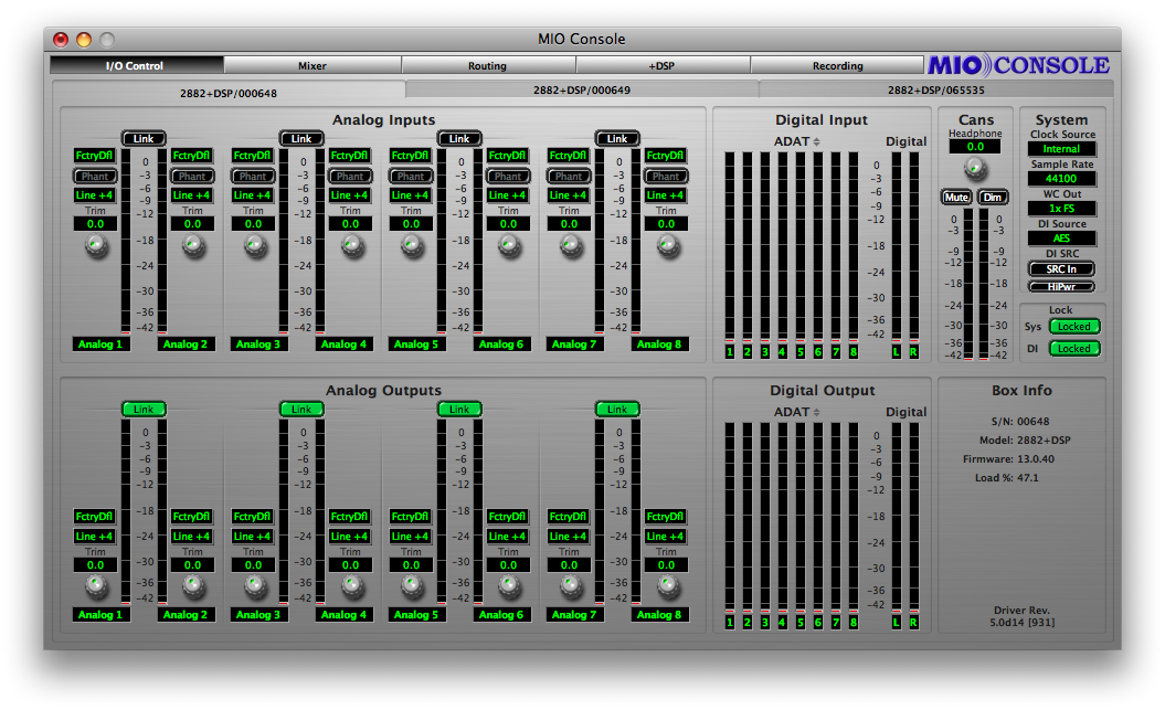
The MIO Console application consolidates all of the controls for the Mobile I/O hardware into one easy to use window. The Mobile I/O has an extremely large number of user configurable parameters and it is very important that you have instant access to the ones that you need. The console provides a thinly layered interface to the entire system and keeps you from having to deal with “Window Overload”.
The MIO Console window has a view panel selector bar that runs along the top of the window. This bar indicates which of the console view panels is currently active. You can tell which panel is active because the button in the bar is “pushed in.” To switch to one of the other panels, simply click on the name of the panel you want to use. The view will change instantly to the one that you have selected.

Under the view panel selector bar is the currently selected view panel. You control the various aspects of the box with the controls in each view. MIO Console has five main panels:
- I/O Panel
- Mixer Panel
- Routing Panel
- +DSP Panel
- Record Panel
I/O Panel
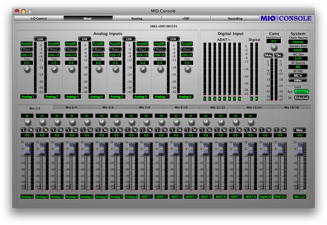
This panel provides full control and metering of all of the analog I/O that the box provides. The top half of the view is dedicated to inputs and the bottom half is dedicated to outputs. You access this panel by clicking on the “I/O Control” button of the view panel selector bar.
Box Tabs
At the top of the panel are Box Tabs — one for each box known to the system. You choose which box you are controlling by clicking on the desired box tab. Boxes can be either Online or Offline. If a box is not connected to the computer but it is known to MIO Console, it will be listed as Offline in MIO Console. You can modify the configuration of an Offline box, and that configuration can be saved, but, of course, the changes will not control the Hardware until it is reconnected to the computer.

MIO Console maintains information about the state of your system persistently. The boxes that have been attached to the computer will be remembered, and their presence in the system can be maintained indefinitely by either the saved system state (saved in your Preferences to maintain the state of the system between launches of MIO Console) or by you explicitly saving the state of the console into a file for later recall (or into a ConsoleConnect host’s session file). In any case, it is possible to have Offline boxes in your system state that refer to a box that you are no longer using. MIO Console provides commands to remove these boxes from the system state.
Each box tab provides a contextual menu that you can popup to apply commands to the specific box. Right-click or control-click the currently active box tab to reveal the popup menu:
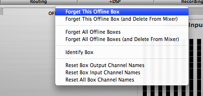
This menu provides the following commands:
- Forget This Offline Box — this command will remove the box from the system state.
- Forget This Offline Box (and Delete From Mixer) — this command is for use with 2d Expanded boxes.
- Forget All Offline Boxes — this command will remove all boxes that are offline from the system state.
- Forget All Offline Boxes (and Delete From Mixer) — this command is for use with 2d Expanded boxes.
- Identify Box — this command will cause a lightshow to appear on the front panel meters of the box associated with the tab. Use this command to identify which physical box is represented by the tab.
- Reset Box Output Channel Names — this command resets all of the user-specified names for output channels to the factory default settings for the hardware.
- Reset Box Input Channel Names — this command resets all of the user-specified names for input channels to the factory default settings for the hardware.
- Reset All Box Channel Names — this command resets all of the user-specified names for the I/O channels to the factory default settings for the hardware.
ANALOG INPUT CONTROL
This varies whether you are using a 2882 or ULN-2; all analog control on the ULN-2 is accessed via the front panel. When looking at the I/O Control tab of the ULN-2, several of the following will be absent. For each analog input channel on the Mobile I/O, you will find a channel strip that contains:
- Parameter Popup control menu (2882 only)
 Parameter Pop-up Menu
- The Parameter Popup control allows you to save, recall, and manage all of the parameters associated with a channel strip in one place. The control is documented in detail here. All presets are automatically shared between all of the input channels.
- Phantom Power enable button (2882 only)
 Phantom Power Button
- The Phantom Power enable button allows you to control whether or not +48v phantom power is applied to the input by the Mobile I/O. This button is only enabled if you have selected Mic or Mic/Pad as the input level standard. If you are using one of the other level standards, Phantom Power is automatically disabled. If you have enabled Phantom Power on this channel, the button will be illuminated bright red. In addition, the Mobile I/O front panel will illuminate the “Phantom” indicator if any of the input channels have Phantom Power enabled.
- Phantom power is appropriate for use with condenser microphones or other devices that can (and must) be powered by the preamp. Mobile I/O limits the amount of phantom power to 10mA per channel, preventing device damage due to shorts. Some (rare) microphones may require more power than is provided by 10mA; you will need an external power supply to power those mics.
- Level Standard popup menu (2882 only)
 Level Standard Pop-up Menu
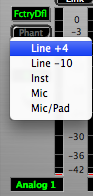
- This control allows you to select the input level and impedance characteristics for the input channel. The available choices are:
- Line +4 — This format supports input levels up to +26 dBu. The input impedance is approximately 10k, and the inline pad is engaged. Phantom power is not available. This format is appropriate for interfacing with professional audio equipment.
- Line -10 — This format supports input levels up to +26 dBu. The input impedance is approximately 10k, and the inline pad is engaged. Phantom power is not available. This format is appropriate for interfacing with prosumer and consumer audio equipment.
- Inst (Instrument) — This format supports input levels up to +6 dBu. The input impedance is approximately 200k, and the inline pad is not engaged. Phantom power is not available. This format is appropriate for interfacing with high output impedance sources like guitar pickups.
- Mic — This format supports input levels up to +6 dBu. The input impedance is approximately 200k (12k with phantom power engaged) and the inline pad is not engaged. Phantom power is available. This format is appropriate for interfacing with dynamic and condenser microphones on low to mid level sources. You may find that for very low level sources, especially with low-sensitivity microphones, that your SNR improves if you take advantage of a high-quality external mic preamp. External preamps are recommended for certain types of recording and microphones, especially classical recording and ribbon mics.
- Mic/Pad — This format supports input levels up to +26 dBu. The input impedance is approximately 10k, (6k with phantom power engaged) , and the inline pad is not engaged. Phantom power is available. This format is appropriate for phantom powered condenser mics that put out near-line level signals (often the case when you are using condenser microphones on bass drums or other very loud sources).
- This control allows you to select the input level and impedance characteristics for the input channel. The available choices are:
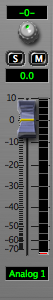
- Gain Trim knob (2882 only)
 Gain Trim KnobThe Gain Trim knob allows you to adjust the analog gain of the input stage over a 40dB range determined by the input standard that you have selected. The gain is indicated in dB relative to the nominal level of the input standard you have selected. The gain changes are smoother near the bottom of the scale, with the steps increasing in size as you reach the +40dB gain limit.
 - Channel Label
 Channel LabelThis simply labels which channel is associated with the channel strip. Click in the lable to edit the channel name.
 - Channel Level Meter
 Channel Level Meter
This is a peak reading, high-resolution, fast PPM meter. It shows the post converter level of the input signal of the associated channel.. The peak hold bar indicates the highest level seen on the channel since the last reset. You can reset the hold by clicking on the meter. These meters are simply high resolution versions of the meters shown on the front panel of the box – all the meter data is generated by the Mobile I/O hardware.
OPTIMIZING INPUT LEVELS
The Analog to Digital converters (ADC) in most devices function best when the peak level is around -6 dBFS (lowest distortion, best sound). This is true of the ADCs in Mobile I/O. Since you have full level control of the input with the gain trim knob, you will find that you get the best quality recordings if you try to set the nominal peak level of the input at about -6 dBFS. In addition to providing the best recording quality, it has the added benefit that you will be operating with an extra 6 dB of headroom before clipping. There is no drawback to optimizing your levels in this way, and plenty of benefit.
ANALOG INPUT CHANNEL LINK (2882 only)
In addition to the channel specific controls, each channel pair shares a Link button. When the Link button is engaged, changes made to one channel of the pair will automatically be applied to the other channel of the pair. This is very useful if you are miking with a stereo pair and need to maintain level balance between the two preamps -- with the Link button engaged, the balance is automatic and exact. When you enable the Link button, the control values for the odd channel in the pair will be copied to the even channel of the pair.

DIGITAL INPUT METERS
To the right of the Analog Input control section is the Digital Input Meter section. This group of meters provides level metering for all of the digital inputs on the Mobile I/O. These meters have the same response characteristics as the analog input meters and show you the audio activity on ADAT channels 1-8 and digital input channels 1-2, going from left to right. The Legacy ULN-2 does not have ADAT I/O
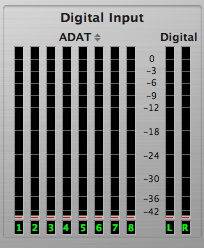
Please note that when the box is clocking at 2x rates (88.2-96k), the ADAT input uses pairs of optical channels to transport the audio, and only channels 1-4 will show activity – channels 5-8 will not display any signal.
The label above the bank of 8 channel meters is a popup control that allows you to select between ADAT inputs and Firewire returns. Click on the control to popup a menu to select between the different modes of operation.
CANS CONTROLS (2882 only)
The next control block to the right is the Cans (Headphones) control section.

The Headphone level control knob provides about 40dB of analog gain control on the headphone output. The Mute and Dim buttons reflect the state of the hardware mute and dim controls for the front panel headphone output. Engaging one of these buttons will also engage the associated control on the hardware.
When the Mute function is engaged, the headphone output will be muted. When the Dim function is engaged, the headphone output will be padded by 18 dB. The meters in this section show the headphone output pre-mute/dim block.
SYSTEM CONTROLS
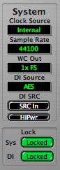
The System block provides controls that adjust various system level aspects of the Mobile I/O hardware:
- The Clock Source popup menu controls the system clock source used by the hardware for digital synchronization and driving the converters:
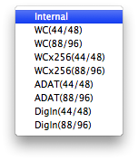 Clock Source Pop-up Menu
- Internal causes Mobile I/O to use its internal clock. You must select this if you want to set the sample rate from the Mobile I/O. If any other clock source has been selected, the console will not allow you to change the sample rate since the sample rate is determined by the external clock source.
- WC (44/48) directs Mobile I/O to clock off of an external Word Clock Source at single rate (e.g. fs = 32k-50k)
- WC (88/96) directs Mobile I/O to clock off of an external Word Clock Source at double rate (e.g. fs = 64k-100k)
- WCx256 (44/48) directs Mobile I/O to clock off of an external 256fs Clock Source at single rate (e.g. fs = 32k-50k)
- WCx256 (88/96) directs Mobile I/O to clock off of an external 256fs Clock Source at double rate (e.g. fs = 64k-100k)
- ADAT (44/48) directs Mobile I/O to clock off of the incoming ADAT stream and run at single rate. All 8 ADAT channels are available. You will generally want to select this source if you intend to use ADAT input.
- ADAT (88/96) directs Mobile I/O to clock off of the incoming ADAT stream and run at double rate. The bottom 4 ADAT channels are multiplexed over the lightpipe to provide 4 channels of double rate audio compatible with other SMUX and Alesis 96k ADAT devices. If you are using a device that provides 4 channels of 96k audio over ADAT optical, you will want to select this clock source.
- DigIn (44/48) directs Mobile I/O to clock off of the selected stereo digital input at single rate (e.g. fs = 32k-50k). This allows operation of the digital input without SRC, and from devices that must supply clock.
- DigIn (88/96) directs Mobile I/O to clock off of the selected stereo digital input at double rate (e.g. fs = 64k-100k). This allows operation of the digital input without SRC, and from devices that must supply clock.
- The Sample Rate popup menu allows you to select the sample rate when you are using internal clock. The Mobile I/O must be running on internal clock for the Sample Rate popup menu to have any effect. If the Mobile I/O is running from an external clock source, you cannot select the sample rate since it is determined by the external clock source.
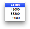 Sample Rate Popup Menu
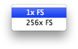
 - The WC Out popup menu allows you to select the output clock signal the Mobile I/O generates on its WC Out BNC connector. The available choices are 1x and 256x. The 1x signal is appropriate for driving devices that accept a Word Clock signal. The 256x signal is appropriate for driving devices that accept 256x or SuperClock signals. Refer to the documentation for the external device to determine what is the most appropriate clock reference for it.
 WC Out Popup
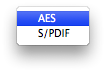
 - The DI Source popup menu allows you to select the active input for the digital input pair. The choices are AES and S/PDIF. This selector physically switches the input to the digital audio receiver between the RCA input and the XLR input.
 DI Source Popup
 - The DI SRC button enables and disables the asynchronous sample rate converter (SRC) in the Mobile I/O digital audio receiver. When the SRC is engaged (button illuminated yellow), the digital audio receiver will automatically synchronize the input signal to the Mobile I/O system clock over a wide range of sample rate ratios.
 DI SRC ButonThis allows you to, for example, digitally transfer a sample from a CD player into a 96k session without any clocking problems. If you want to make bit-transparent transfers, you will need to disengage the SRC and ensure that the Mobile I/O and the external device are both using the same digital audio clock via one of the Mobile I/O synchronization mechanisms.
 - The Lock indicators show which elements of the Mobile I/O clocking system are properly locked. The clocking system must be locked for the unit to behave as expected. If the system is not locked, audio will play at the wrong rate and will be distorted or noisy. Under normal circumstances, the system should always be locked, but if you have selected an external clock source and the clock signal is not present, corrupted or out-of-range, the system may unlock. There are indicators for the system and the digital input.
 Lock Indicators
ANALOG OUTPUT CONTROL
The bottom half of the panel is dedicated to the hardware outputs of the Mobile I/O. Much like the analog inputs, each of the analog outputs has a set of controls associated with it. The controls are similar to the analog input controls. Again, many of these controls do not apply to the ULN-2. Each output channel has:
-
Parameter Popup control (2882 only) — The Parameter Popup control allows you to save, recall, and manage all of the parameters associated with an analog output in one place. The control is documented in detail here. All presets are automatically shared between all of the output channels.
Level Standard popup menu (2882 only) — This control allows you to select the output level for the channel. The available choices are:
- Line +4 — This format supports output levels up to +26 dBu. The standard setting with the trim knob set to 0dB yields a +24dBu output when the digital signal driving the DAC is 0dBFS. This corresponds to +4 dBu nominal with 20dB of digital headroom. You can use the trim knob to adjust the analog output level to be consistent with the needs of other audio gear. The output impedance is approximately 50 Ohms. This format is appropriate for interfacing with professional audio equipment.
- Line -10 — This format supports a nominal output level of -10dBV with 20 dB of digital headroom. You can use the trim knob to adjust the analog output level to be consistent with the needs of other audio gear. The output impedance is approximately 50 Ohms. This format is appropriate for interfacing with prosumer and consumer audio equipment.
Gain Trim knob (2882 only) — The Gain Trim knob allows you to adjust the analog gain of the output stage (post DAC) over a 40dB range determined by the output standard that you have selected. The gain is indicated in dB relative to the nominal level of the output standard you have selected. The gain changes are smoother near the bottom of the scale, with the steps increasing in size as you reach the +40dB gain limit. Unless the signal is quite low, you will put the output stage into analog clipping well before you hit the 40dB gain limit.
- Channel Label — This simply labels which channel is associated with the output.
- Channel Level Meter — This is a peak reading, high-resolution fast PPM meter. It shows the pre converter level of the output signal of the associated channel. The peak hold bar indicates the highest level seen on the channel since the last reset. You can reset the hold by clicking on the meter. These meters are simply high resolution versions of the meters shown on the front panel of the box – all the meter data is generated by the Mobile I/O hardware.
ANALOG OUTPUT CHANNEL LINK (2882 only)
In addition to the channel specific controls, each channel pair shares a Link button. When the Link button is engaged, changes made to one channel of the pair will automatically be applied to the other channel of the pair. This is very useful if you are driving a stereo monitor section or stereo device. By engaging the Link button, you will ensure that both channels have precisely the same amount of analog gain applied post DAC. When you enable the Link button, the control values for the odd channel in the pair will be copied to the even channel of the pair.
DIGITAL OUTPUT METERS
To the right of the Analog Output controls is the Digital Meters section. This group of meters provides level metering for all of the digital outputs on the Mobile I/O. These meters have the same response characteristics as the analog output meters, and show you the audio activity on ADAT output channels 1-8 and digital output channels 1-2, going from left to right. Please note that when the box is clocking at 2x rates (88.2-96k), the ADAT output uses pairs of optical channels to transport the audio and only channels 1-4 will show activity, channels 5-8 will not display signal. Both channels of the stereo digital output remain active at all sample rates.
As with the digital inputs, the ULN-2 does not have ADAT connectivity. This can be added via a 2d card upgrade.
BOX INFO
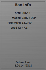
The Box Info section of the panel, in the lower right-hand corner of the window, shows you information about the currently connected and selected Mobile I/O unit. This section displays the Serial Number, Model Information and Firmware revision of the connected box. All of this information can be useful in trying to track down any connection problems that may arise.
If there is no information displayed in the Box Info section, the software is not communicating properly with the Mobile I/O hardware, or there is no Mobile I/O present on the FireWire bus.
If the FireWire light on the front panel of the Mobile I/O is illuminated but the box information does not appear in the console window, it is very likely that the software has not been installed properly. If this is the case, please refer to the installation instructions for details on how to properly install the software.
If, on the other hand, the FireWire light on the front panel of the Mobile I/O is not illuminated, the box is not communicating properly with the computer. Please check the cabling of your Mobile I/O and other devices on the FireWire bus and make sure that everything is connected correctly. If that does not properly establish the connection, try rebooting your computer. As a last resort, try connecting only the Mobile I/O to the computer to ensure that communication can be established.
MIXER PANEL
The Analog I/O panel provides all of the bread-and-butter functionality that you would expect from a flexible audio interface like Mobile I/O - what you need to get the job done quickly and easily. The Mixer panel provides features that you won’t find anywhere else – here is where things start to get really interesting.
MIXER CONTROLS OVERVIEW
Each mixer has controls for Level (fader), Solo (button), and Mute (button) for each channel. Each stereo mixer also includes a pan control (knob) for each mono channel. For stereo inputs, such as the defaults of the digital inputs or your DAW output, will not have a pan knob. Instead, the two individual channels that make up the pair will be hard panned, and the fader meters will appear as stero meters.
At the far right of each mixer surface is the Master Fader. This fader will be Mono for Mono Mixers and Stereo for Stereo Mixers. Above the Master Fader is a bus mute button that allows you to quickly mute the entire mixer.
Each mix bus can have up to 36 inputs assigned to it. All of the analog, digital, and ADAT hardware inputs are available in each mixer. You can also assign any (or all) of the CoreAudio playback channels from your DAW to each mixer. Since there are 18 hardware inputs and 18 DAW return busses that are routed from the CoreAudio driver on the host computer, you can mix up to 36 channels on each bus.
The default state of the hardware input channels in the mixers is faders at unity, mutes on, solos off and center panned. The playback channels from your DAW are unmuted in pairs per bus (e.g. DAW 1/2 will be unmuted on Mix 1/2, DAW 3/4 will be unmuted on Mix 3/4, etc.) MIXER PANE TABS
Use the tabs above the pan knobs to select the mixer you want to control. Each tab represents a mixer you have configured in the routing panel. When you click on a tab, the controls will be instantly updated to reflect the state of the associated mixer. In this way you can quickly switch back and forth between multiple independent mixes, each with a full mixing interface.

Each mixer also has a Parameter Popup control associated with it. Unlike the Input and Output controls, the parameter control popup does not have an explicit user interface element representing it. Instead, the popup is accessed from the mixer’s tab itself. To pop-up the menu, you either click and hold the tab, or <control>-click the tab. The parameter popup menu allows you to maintain a library of standard mix configurations, scenes, and setups. It also provides a very quick method for copying mixes from one bus to another.
CHANNEL FADERS
The Channel fader controls the relative level of the input channel in the mix. It works just like its non-virtual counterpart. The calibration numbers to the left of the fader knob provide an accurate guide to the amount of gain that will be applied by the fader. The label area above the fader knob lets you know which input channel the fader is controlling. The labels default to the console’s default names for the channels, but you can rename the channels to more meaningful names using the naming controls in the Routing Matrix.
The exact amount of gain for the fader is displayed in the small black window above the fader channel label. If you want to set a channel gain precisely, simply click in the small black window and type in the desired gain in dB numerically. Hitting the <return> key or clicking outside the entry box makes the new setting take effect. Hitting the <tab> key will make the new setting take effect and will move to the next numeric entry field in the mixer.
The gain range for each channel is from -∞ (muted) to +10 dB. The resolution of the gain control is extremely fine and gain changes are interpolated in the mixer, so there is no zipper noise when you make continuous (or even discontinuous) gain changes. <command> clicking the fader knob will allow you to make fine adjustments to the fader level by dragging the mouse up and down. <option> clicking the fader knob will reset the fader to unity gain. Clicking the meter associated with the fader will clear the peak holds for that channel.
For mono channels, the current gain is applied to the channel before the pan. For stereo channels, the current gain is applied uniformly to both of the hard-panned input channels.
CHANNEL METERS
Each channel fader has a meter (or a pair of meters for stereo channels) associated with it. The meters are calibrated consistently with the fader calibration. Each meter is a peak reading, fast-PPM meter that is pre-fader. The peak hold bar shows the biggest peak since the last reset. Clicking on a meter will clear the peak holds for that channel.
CHANNEL PANS
Each mono input in a stereo mixer has a pan knob above the fader. The pan knob allows you to control the relative amount of the input channel that is placed into the two busses of the stereo mixer. Panning hard left (L100) means that the channel will appear at full volume in the left (odd) bus of the mixer. Panning hard right (R100) means that the channel will appear at full volume in the right (even) bus of the mixer. When the channel is center panned, the signal appears at a decreased volume (-3dB) in both channels, such that the volume of the total signal in both channels is equivalent to full volume in one channel. As you pan from left to right, the signal is distributed between the two channels so that the total volume remains constant.
As with the channel fader, the black window above the channel pan knob provides a precise readout of the current pan position, and clicking on the black window will allow you to type in an exact pan amount. Negative numbers (-100 to 0) indicate left pans and positive numbers (0 to 100) indicate right pans. 0 is center pan. <option> clicking the pan knob will return it to center pan, and <command> click-dragging the knob will allow you to adjust the pan position in finer increments.
MUTE BUTTONS
Each input has a Mute button (labeled “M”) associated with it. When the mute button is engaged (illuminated white), the channel will be muted in the mixer. The mute is interpolated, so muting a channel will not cause audible clicks. <option>-clicking a mute button will set all of the mutes on the mix bus to the same state as the button you click. This allows you to quickly mute all the channels or quickly unmute all the channels on a bus.
SOLO BUTTONS
Each input has a Solo button (labeled “S”) associated with it. When the solo button is engaged (illuminated red), only channels that have been soloed will be mixed by the mixer. The other channels will effectively be muted. As with the mute button, the gain changes associated with soloing or unsoloing a channel are fully interpolated and will not cause audible clicks. <command>-clicking a solo button will exclusively solo the associated channel. The <command>-click will automatically clear the solo state of all other channels on the mix bus. <option>-clicking a solo button will set all of the solos on the mix bus to the same state as the button you click. This allows you to quickly solo all the channels or quickly un-solo all the channels on a bus.
MIXER MASTER FADER
The Fader that appears on the right side of the mixer pane is the Mix Master Fader. This fader controls the overall bus level of the mix bus. Operationally, it is exactly the same as the channel faders (see: Channel F). Each Mix bus in the system has 24 dB of headroom above full scale. If the summing point of the mix bus is clipping, you can pull the mix out of clipping by dropping the Master fader, as long as the sum point is clipping by less than 24 dB.
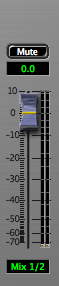
MIXER MASTER MUTE
Each mix bus has a master mute button above the master fader that allows you to mute the output of that mixer. This mute is interpolated.
WIDE MIXERS
As was described before, the integrated mixers in Mobile I/O are WIDE – that is they allow you to mix every available input channel (both hardware channels and FireWire channels) together. In the widest case, the mixer will have 36 faders to allow you to control the gains for all of the input channels.
The MIO console window is only wide enough to accommodate 18 faders plus the Master fader. If you have enabled more channels than will fit in the window, the MIO console will automatically display a scrollbar at the bottom of the Mixer pane. Use this scrollbar to control which faders are visible at any given time. The width of the scrollbar indicator shows you how many of the enabled channels are visible at any given time. The scrollbar will automatically be hidden if you reduce the number of inputs to the mixer below 19 channels or if you switch to a different mixer that has less than 19 channels enabled.
TIP: Mobile I/O’s support of near-zero latency mixing of every channel opens up a huge variety of applications that cannot be achieved with standard interfaces or, at the very least, require external gear or major work-arounds to accomplish. Some examples are:
- Stem-based mixing.
- In this mixing technique, you mix disparate elements of the program to separate sub-mixes called stems. You might mix drums to one stem, instruments to another, and vocals to a third. Then the relative balances of the mix can be addressed later in a macroscopic way (during mastering, for example). This also enables remixing the project easily without having to go back to the multi-track master. Since you will be creating stems on individual busses in the DAW, you need to sum the stems for monitoring. This is easily accomplished with Mobile I/O’s mixer.
- Monitoring mixed-in effects sends when the external effects are unavailable.
- This is Mobile I/O, right? You may find that you want to continue editing or mixing while you are away from the studio. You can use the WIDE mixer in Mobile I/O to mix in DAW effects send busses for monitoring without having to reconfigure your DAW session.
- Multichannel foldback mixes.
- Ever tried monitoring a full drum kit with a host-based foldback mix, or even a 2 channel cue mix? It can’t be done! At least, it can’t be done well). To monitor multichannel input tracking sessions you need an external mixer – or the built in WIDE-mixer in Mobile I/O.
- If you take advantage of MIO’s ADAT input with a third party A/D converter (or a second MIO) with ADAT outputs, you can simultaneously track and mix up to 18 input channels, with no latency, and no external mixer!
- Near-Zero Latency monitoring of external effects.
- Most singers need some reverb or other effects to get the feel right during their performance. With Mobile I/O and the WIDE mixer, you can split off a send from the performer’s input channel, send it to an external effects unit, and mix the effect return into the performer’s foldback mix -- with virtually no latency.
- Multiple WIDE mixes
- Since Mobile I/O supports multiple WIDE mix busses simultaneously, you can form multiple, individual foldback mixes for multiple performers at the same time, and best of all, each mix has its own complete mixer control surface, so you don’t have to mess around with a million unreadable aux send knobs.
ROUTING PANEL
The third panel in the MIO Console window is the Routing panel. This panel is what you use to access the powerful routing features that you won’t find anywhere else. The Routing Matrix portion of the panel lets you dynamically control the configuration of the WIDE mixing engine and also configure the channel names for the hardware. You access this panel by clicking on the “Routing” button of the view panel selector bar at the top of the console window.
- The Output Patchbay on the left side of the panel.
- The Routing Matrix on the right side of the panel.
THE ROUTING MODEL
The Routing Panel provides a user interface for controlling the underlying routing architecture of the Mobile I/O on legacy boxes. The routing architecture provides a powerful routing model to allow you to control the routing of signals between physical & virtual inputs and the hardware mixer & physical outputs.
Conceptually, the architecture is quite simple:
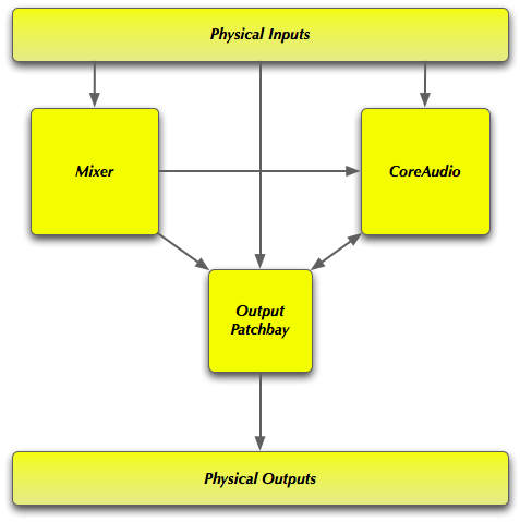
All of the physical inputs (e.g. Analog, ADAT and Digital), all of the channels being transmitted over the FireWire bus from the CoreAudio Application (e.g. DAW), and all of the outputs from the Mobile I/O WIDE Mixer are available to the Output Patchbay. The Output Patchbay can cross-point assign any of its inputs to any of the physical outputs (e.g. Analog, ADAT and Digital).
All of the physical inputs and all of the channels being transmitted over the FireWire bus from the CoreAudio Application are also inputs to the Mobile I/O WIDE Mixer. Every bus has each of those inputs available for mixing. The mixer outputs are sent to the Output Patchbay for routing to physical outputs. The number of mix busses varies with the Mobile I/O hardware model and the sample rate. The Mobile I/O 2882 supports 10 mono (5 stereo) mix busses at sample rates up to 50kHz (e.g. 1x rates) and 4 mono (2 stereo) mix busses at sample rates up to 96kHz (e.g. 2x rates).
Every physical input is mult’ed from the router/mixer section and sent directly over the FireWire bus to the CoreAudio host. Regardless of any mixing, routing, or mult’ing that you configure in the hardware, you can always record all of the inputs with your DAW.
As you can see from this simple, high level view, the Mobile I/O routing architecture supports direct routing of any input to any output and also mixing of any set of inputs to multiple mixers. The outputs of the mixers can be routed to any output or any set of outputs for hardware mults. All hardware inputs are available to the CoreAudio host.
As it turns out, the Mixer/Router in Mobile I/O is quite extensive and the simple user interface hides a lot of complexity:
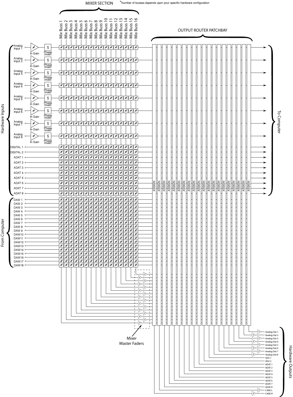
As you can see from this schematic diagram of the mixer/router, the Mixer in Mobile I/O is a fully cross-pointed matrix. While we are presenting the mixer to you as a set of mono and stereo mixers, the actual underlying structure is a full matrix. This means that the mixer is ready for surround and multi-channel matrix mixing today. The schematic provides an accurate representation that shows the signal flow through the mixer and into the router with all analog and digital gain points represented.
OUTPUT PATCHBAY DETAILS
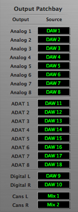
The Output Patchbay allows you choose the signal sources to send to the hardware outputs. You can feed any output from your choice of a mix bus, a hardware input, or a FireWire input from the computer.
PATCHBAY POPUP CONTROLS
The output patchbay is the set of popup menus on the left side of the panel. Each popup menu corresponds to the hardware output that is labelling it. The channel that you choose from the popup menu will drive the associated hardware output.
Since the output patchbay is fully cross-pointed, you can easily construct direct routes from hardware inputs to hardware outputs for stand-alone converter operation, routes from CoreAudio (using the DAW channels) to the outputs for direct dubbing and monitoring from the computer, and routes from the mixer to hardware outputs for foldback, monitoring, and effects sends.
The output patchbay even lets you send the same channel to multiple outputs, which makes it really simple to create channel mults. You can use this to:
- send multiple copies of an aux group to different effects devices
- manage monitoring on multiple monitor systems (big and small)
- monitor on analog outputs and record on digital outputs
- send the same monitor mix to multiple outputs for multiple performers
- record safety mixes on digital two-track recorders while multitrack recording to the hard drive
To choose a source for an output channel, simply go to the popup menu for the output you want to route to, click and select the source send. Each popup window is like the jack of a patchbay, and each name in the popup menu is like a patchbay cable that carries the named signal.
PATCHBAY PARAMETER POPUP CONTROL
Directly above the patchbay popup menus is the “patchbay parameters” parameter popup control. This control allows you to store patchbay configurations for later recall. See the section patchbay popup controls, for more details about the parameter popup menu.The factory default routing for Mobile I/O configures the box to behave as a direct-routed audio interface – all the inputs go directly to the computer, all the outputs from the computer are directly routed to the hardware outputs, and the Headphone output is fed by the stereo mixer on Mix 1/2. This makes the Mobile I/O act like a basic audio interface.
Other configurations that may be very useful include:
- cross routing the analog inputs and outputs with the ADAT I/O – use this for 8x8 A/D/A operation (an upgrade for your ADAT or digital mixer!)
- direct routing of analog inputs to AES/SPDIF (2 channel Pre/DI/ADC)
- switching mults of the mixer outputs for alternate monitor configurations.
This control allows you to maintain a library of frequently used routings and switch between them at will. Spend a little time to familiarize yourself with it — it is extremely powerful.
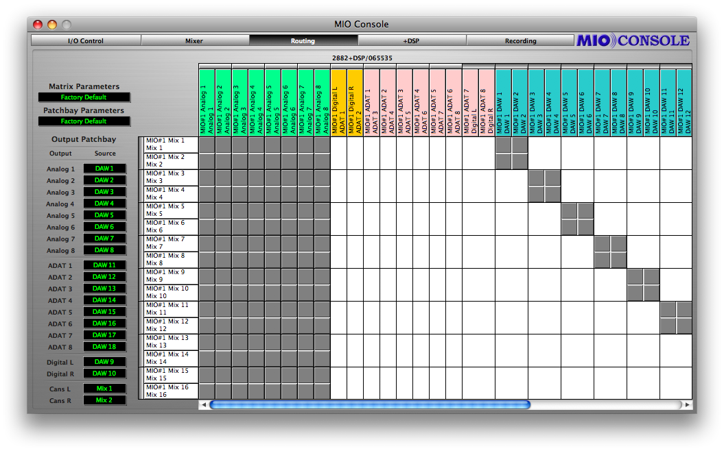
ROUTING MATRIX DETAILS
The Routing Matrix (Matrix) is the mixer assign matrix that is on the right side of the pane (see “Routing Panel” ). This control surface allows you to fully configure the structure of the multi-bus WIDE mixer in the Mobile I/O hardware. It also allows you to name all of the hardware and virtual channels that are accessible in the hardware.
You use the Matrix to assign hardware and FireWire inputs (DAW outputs) to mixers in the Mobile I/O. To assign channels to a given mix, you click on a crosspoint in the Matrix, darkening the associated Crosspoint Assign tile. Deselecting a tile removes the associated fader from the mixer and mutes the channel in the hardware.
The WIDE mixer allows you to assign all of the hardware input channels and all of the FireWire channels to each mix bus. By limiting the number of channels assigned to any given bus, you can reduce the complexity of the associated mixer interface.
LOGICAL DESCRIPTION
Each mix bus and each input channel has a path label tile associated with it. These tiles are arrayed along the top and left edges of the Matrix.
The tiles along the top edge of the Matrix are the input path tiles. Each tile is color coded based upon the type of input it is:
- Green for Analog Inputs
- Orange for Digital Inputs
- Pink for ADAT Optical Inputs
- Blue for FireWire Inputs (Outputs from the DAW)
Each tile shows the Mobile I/O unit it is associated with, the physical name for the path, and the user defined name for the path.
Above each pair of input tiles is a thin tile that is used to join two input paths into a stereo input channel. In the factory default configuration, the Digital Inputs are joined into a stereo pair and each pair of DAW channels is joined into stereo pairs. If the channels are joined into a stereo pair and the pair is assigned to a stereo mixer, the pair will be represented by a single stereo fader in the mixer interface, and no pan knob will appear.
The white tiles along the left edge of the Matrix are the Mix bus tiles. All of these tiles are white because they all represent mix busses. Each tile shows the Mobile I/O unit it is associated with, the physical name for the mix bus, and the user name for the mix bus.
To the left of each pair of Mix tiles are thin inset tiles that are used to join two mix busses into a stereo bus. If the busses are joined, the associated mixer will have pan knobs for each of the mono hardware channels. If the bus is a mono bus, there are no pan knobs associated with the input channels.
The interior of the Matrix is composed of a large number of square crosspoint assign tiles. The Matrix is too wide to fit completely within the MIO Console window; you may use the scrollbar that appears at the bottom of the Matrix to scroll the remaining DAW channels into view.
Each crosspoint assign tile indicates whether or not the input channel at the top of the column is assigned to the mix bus at the edge of the row. If the tile is filled in, the channel is assigned to the mix, and the controls for that channel will appear in the associated mixer. If the crosspoint tile is not filled in, the channel is not assigned to the mix, and the controls will not appear. The channel will be muted and un-soloed on the associated mix bus.
Stereo pairs are automatically assigned as a group to busses.
There are some keyboard shortcuts that you can use when making Matrix assignments:
- clicking in one tile, followed by <shift>-clicking in another tile will automatically select or deselect all of the tiles in between the endpoints; the selection will match the new state of the tile at the second click location
- clicking and dragging in the Matrix will continuously apply the new assignment state to each tile you drag over
- <command>-click dragging will scroll the Matrix
CONFIGURING CHANNEL NAMES IN THE MATRIX
MIO Console has fully user configurable channel names. The names that you select for your channels will propagate to all of the other aspects of the MIO Console user interface.
This allows you to name the channels in meaningful ways. The analog inputs can be named to match the sources. The Digital I/O can be named to match the effects device that you have patched. Mixes can be named by the foldback monitor or effects send that they will feed.
To name a channel, click on the input path tiles (for input channels) or the mix bus tile (for Mix busses). The channel configuration window will appear above the MIO console window:
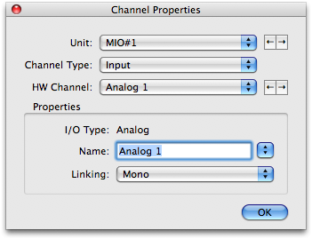
All of the channel identification controls will be set for the tile you clicked on. To change the user selectable name of the channel, simply type the new name. The name will be updated in the console when you do one of the following things:
- Hit the <return> key. This will update the name and dismiss the window.
- Hit the <tab> key. This will update the name and switch to the next channel in the list.
- Hit <shift><tab>. This will update the name and switch to the previous channel in the list.
- Select any other channel using the popup menus or the “<“ or “>” buttons in the channel configuration. This will update the name and switch to the new channel selection.
You can dismiss the window without updating the channel name by clicking its close box.
You can also select the stereo linking state from Linking popup menu in the channel configuration window. The state will be updated in the console along with the channel name.
The channel identification controls identify which channel you are adjusting:
- The MIO Box popup menu allows you to select which Mobile I/O you want to configure if more than one Mobile I/O is present on the bus.
- The Channel Type popup menu lets you switch between input channels and mix busses.
- The HW Channel popup menu identifies which hardware channel you are adjusting.
- The < button associated with the MIO Box and HW Channel popup menus steps to the previous item in the associated list.
- The > button associated with the MIO Box and HW Channel popup menus steps to the next item in the associated list.
MATRIX PARAMETER POPUP
The entire state of the matrix can be saved to and recalled from the console parameter library system. The basic functions of the parameter popup control are documented in the next section. Since you are very like to have a number of tracking and mixing configurations you use over and over again, the Parameter Popup for the Matrix is a real timesaver. This control appears in the top left corner of the pane, above the Parameter Popup control for the Patchbay router. Each time you create a configuration that you are likely to use again, save it in the Parameter Library for instant recall when you need it next.PARAMETER POPUP CONTROLS
The Parameter Popup control is MIO Console’s unified mechanism for handling presets for the various sections of the Mobile I/O. Each element of the console that supports the Parameter Library mechanism has a parameter popup control associated with it. These elements currently include:
- Input Channels
- Output Channels
- Mixers
- Output Patchbay
- Matrix
Each instance of the Parameter Popup control provides the same commands and options for every section of the console.
POPUP COMMANDS
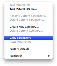
The parameter popup provides a hierarchical, categorized library of configuration presets for the associated section of the console. The menu is divided into three portions. The first portion consists of all of the items above the “Factory Default” item. The second portion is the “Factory Default” item and the third portion is the hierarchical items below the “Factory Default” item (see Parameter Popup Menu ).
The commands in the first portion of the menu allow you to save and manage the presets in the library. All of the presets are shared between like elements in the console. The preset commands are:
- Save Parameters — use this command to save the current state of the associated console settings to the currently selected preset (will appear as “Save Parameters As…” if there is no currently selected preset)
- Save Parameters As… — use this command to name and select a category to save the current state of the associated console settings as a preset into the library
- Rename Current Parameters… — use this command to rename the currently selected preset
- Delete Current Parameters — use this command to remove the currently selected preset from the library
- Create New Category — use this command to add a new category to the library
- Delete Category — use this command to delete the currently selected category and all of its associated presets
- Copy Parameters — use this command to copy the current state of the associated console settings to the clipboard; you can use this to copy your settings from one block to another
- Paste Parameters — If the clipboard contains compatible settings, this command will be available and will set the current state of the associated console settings to the settings on the clipboard. Use this with the “Copy Parameters” command to duplicate settings from one channel to another or from one mix to another
The “Factory Default” command will set the current state of the associated console settings to the default settings.
POPUP PRESETS
In the third part of the menu, each of the categories will be listed as a hierarchical menu title. Each of the presets for each category will be listed in the submenu under the category menu. The currently selected category and preset are drawn in bold, so you will know what is currently active.
Selecting a preset from the menu will make that preset active and will set the current state of the associated console settings to the values contained within the preset. The name of the currently selected preset will be drawn in the popup area in the console window to indicate which preset is active.
If you change the settings in the console, the name of the preset will be drawn in italics indicating that the current settings differ from the selected preset.
For the Input and Output channels, you can hold down the <option> key while selecting a preset to automatically apply the preset to all of the other input or output channels.
To access the parameter popup for the mixers, either click and hold the associated mixer tab or <control> click the associated mixer tab.
We have provided an initial set of presets for the various parameter libraries. The presets for the output channels are relatively complete and give you an idea of the power and flexibility of this approach to parameter management.
PERSISTENT STATE MANAGEMENT
All Mobile I/O hardware has support for setting a Boot State — the configuration the hardware will use when the unit boots up. As of v.5 of the Mobile I/O software, this boot state includes the entire state of the unit including the configuration of the mixer, the router, sample rate, clocking analog I/O levels (for HW that has digital control), and +DSP configuration.
This functionality allows you to fully configure your hardware and “pour” a complete digital signal processing engine into the HW for instant-on processing.
To configure the Boot State for your Mobile I/O:
- First, attach the Mobile I/O to the computer and start up MIO Console.
- Use MIO Console to configure the box. Set up all aspects that you care about. Once you have the configuration as you like it, you are ready to save the snapshot.
- Choose the “Save Boot State” command from the “Utilities” Menu
The ULN-2 hardware extends the Boot State and adds support for Persistent State Snapshots. There are 10 snapshot slots in the ULN-2 that are recallable from the controls on the ULN-2 front panel. Each Persistent State Snapshot contains a complete description of the state of the box, including Sample Rate, Clock Source, Digital input source, Sample Rate Converter Enable, Patchbay routing, Mixer Configuration, Levels and +DSP configuration and routing. In other words, a snapshot saves every aspect of the configuration of the ULN-2.
The first snapshot slot is special as it is used by the unit to configure the hardware and the routing when the ULN-2 starts up. The other 9 slots are available for storing alternate configurations that can be selected “on the fly” after the ULN-2 is up and running.
When a computer is attached to the ULN-2, the front-panel controls to select snapshots are locked-out since the computer is actively controlling the configuration of the box.
If the computer is not attached, the two tact-switches on the left-side of the front-panel (between the status indicators and the meters) may be used to select the snapshot that you want to use to configure the ULN-2. These buttons are labled with up and down arrows. The currently selected snapshot is indicated by the column of LED’s labled C, 1, 2, 3, 4, 5, 6, 7, 8, 9. When the ULN-2 turns on, the “C” indicator will be illuminated, indicating that the unit has booted up with the state that was stored in the “Boot Snapshot”.
Pressing the up arrow will move to the next higher snapshot in the list (e.g. if you are currently on snapshot 3, you will move to snapshot 2). Conversely, pressing the down arrow will move to the next lower snapshot in the list (e.g. if you are currently on snapshot 3, you will move to snapshot 4). If you are at either beginning of the list and you press the up arrow, you will wrap around to the last item in the list. When you select a new snapshot, the new snapshot is applied to the box immediately.
In order to configure the boot state and snapshots for your ULN-2, you will need to utilize the MIO Console application. Configuring and storing snapshots in the box is very simple:
- First, attach the ULN-2 to the computer and start up MIO Console.
- Use MIO Console to configure the box. Set up all aspects that you care about. Once you have the configuration as you like it, you are ready to save the snapshot.
- Choose the appropriate save command from the Utilities Menu
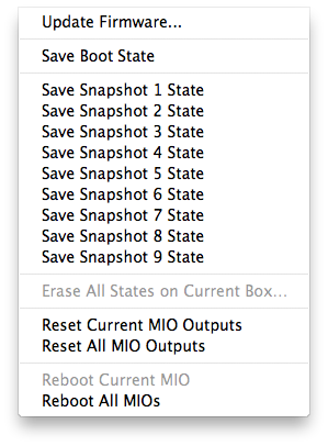 Utilities Menu
- To save the snapshot to the “Boot State” slot, choose the “Save Boot State…” item.
- To save the snapshot to one of the other snapshot slots, choose the appropriate “Save Snapshot x State…” item (where x is the appropriate number).
- Save a copy of the current Console state to a file on your hard disk with an appropriate name (like “ULN-2 Snapshot 1” for the 1st snapshot) so that you have a copy of the state on the computer if you want to modify it in the future.
With v.5, the 2882 supports an alternate boot state as well. This is the state that is saved in the “Snapshot 1” state slot. If there in nothing saved in this slot, the alternate boot state will be the factory default boot state.
To access the alternate boot-state on the 2882, simply hold the front-panel DIM button while powering the unit. This will select the alternate boot state.