Routing Applications for 2d Expanded Units
Routing Applications
This document provides a hands-on description of how to configure the mixer and router for a somewhat complex tracking situation. This document is only for 2d Expanded units. You can compare this document to corresponding document (Routing Applications for Unexpanded Units) for un-expanded units to see how much easier the process has gotten with the 2d Card and the v.5 mixer.
EXAMPLE SETUP
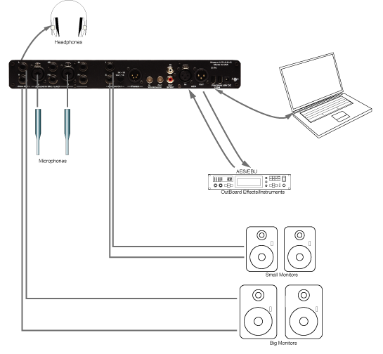
In this section we will go step by step through an application that is possible with a ULN-2 configured as shown in illustration Example ULN-2 Setup above. After reading this section you should have a feel for how to apply Mobile I/O’s routing and mixing capabities.
EFFECTS FOR TRACKING
Many performers (especially singers) find it easier to get a good take if they have some sweetening effects in their headphone mix while tracking. These will usually be temporary effects and will not necesarily make it into the final mix but they can make the difference between a good take and a bad take.
In previous versions of the Mobile I/O, we would have to use an external effects device connected to Mobile I/O’s AES ports to add some reverb to the headphone mix we make in MIO Console, but with the introduction of the 2d Card, we can add reverb “In the Box”. You can still use the AES ports to add other effects if desired.
SETTING UP THE ROUTING
The first thing we need to do is configure our mixers and routing. For this setup we will use two mix busses in MIO Console: one for the actual headphone mix and one for the send mix to the reverb. To do this we need to bring up the Mixer Config sheet for the v.5 mixer:
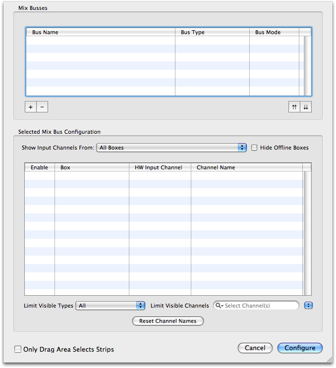
Add two busses to the mixer by clicking the + button in the Mix Busses section twice. Double click the first bus to name it, and tab to name the second bus. Also, set the Reverb bus’s Bus Mode to Aux Bus:
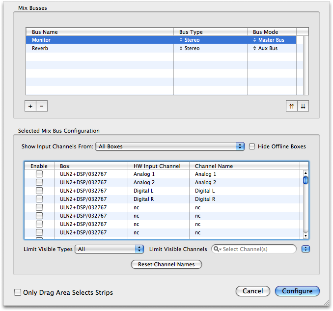
After you have created the busses, you still need to assign the desired inputs to the Monitor bus. To do this, first select the Monitor bus in the Mix Busses list and then just click the check boxes for the inputs you need in the Selected Mix Bus Configuration list
- Analog 1
- Analog 2
- DAW 1/2 (a stereo channel towards the bottom of the list)
- Reverb (the Reverb Bus — it is at the bottom of the list)
In addition, if you would like to use any of the other inputs (AES or ADAT), you can simply add them to the bus by clicking the proper check boxes in the list.
You don't need to add any of the inputs to the Reverb bus — we’ll do that with sends in the mixer.
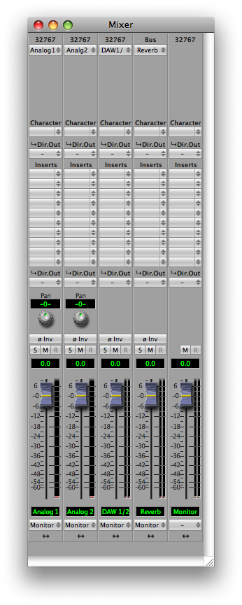
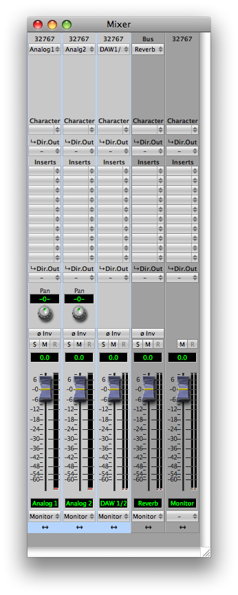
Click the Configure button, and MIO Console will configure the basic mixer for you:
Now we need to add sends to get the audio from the inputs to the Reverb bus. This can be done in bulk by selecting the desired input strips and then inserting the send in one of the insert slots.
First select the strips:
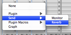
Then insert the send:
After you have done this, the Sends window will appear, and each strip will have a send inserted:
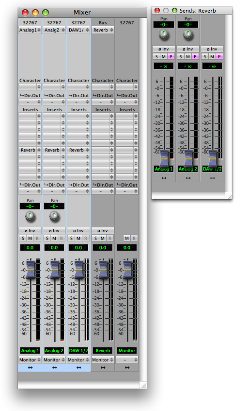
As you can see, you now have a fader and panner for each send that you can use to set the level and pan of the signal into the reverb. The lavender colored P buttons on each send strip make the send strip Post Fader when enabled, and Pre Fader when disabled.
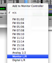
We still need to route the Monitor Mix to the headphones. This is done directly from the Master Fader strip output popup at the very bottom of the Monitor strip:
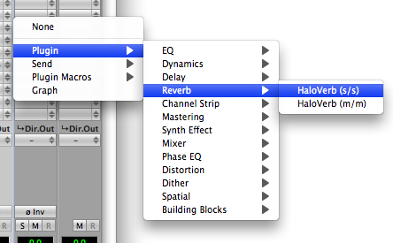
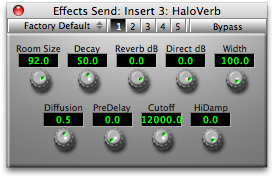
Finally, we need to add a HaloVerb reverb plugin to the Reverb bus return:
Now everything is basically configured. You can set up the dry headphone mix on the main faders in the Mixer window. Once we have basic balances set, you can switch to the Send window. In the Send mixer we can unmute each channel and set its send level to the reverb. If you want it to match the levels of the dry headphone mix, you can ensure that all the sends are Post Fader and all the send faders are set to unity gain. If you would rather set the reverb send levels independently of the dry mix, you can make the sends Pre Fader.
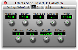
Tweak the HaloVerb settings to taste. Notice that even if you set the Direct dB parameter back to 0 dB there is no phasing introduced, because the v.5 mixer is absolutely phase coherent, even with routing between multiple busses.
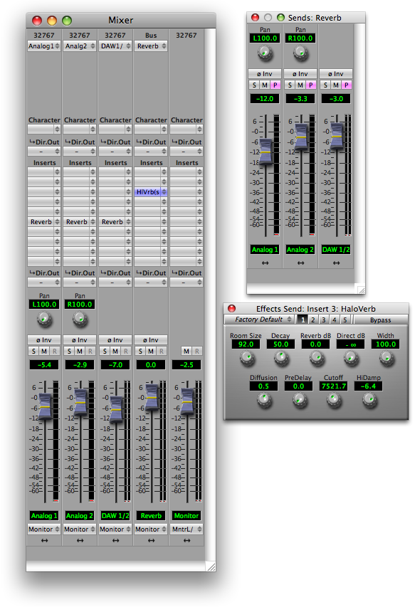
Your final configuration will look something like this:
If you want to use this example as a tracking set up, choose Save As... from the file menu. This brings up a standard Macintosh save dialog and allows you to save the entire state of MIO Console as a setup document.
Controlling Multiple Monitors
You can use the Monitor Controller features of Mobile I/O to set up multiple monitor paths and easily switch between them. The Monitor Controller is an intelligent router and volume controller that was designed specifically to manage monitoring systems.
For this example we will work with a 2882 and have two sets of powered monitors connected to the Mobile I/O. The first set will be connected to Analog Outputs 1-2 and the second to Analog Outputs 3-4.
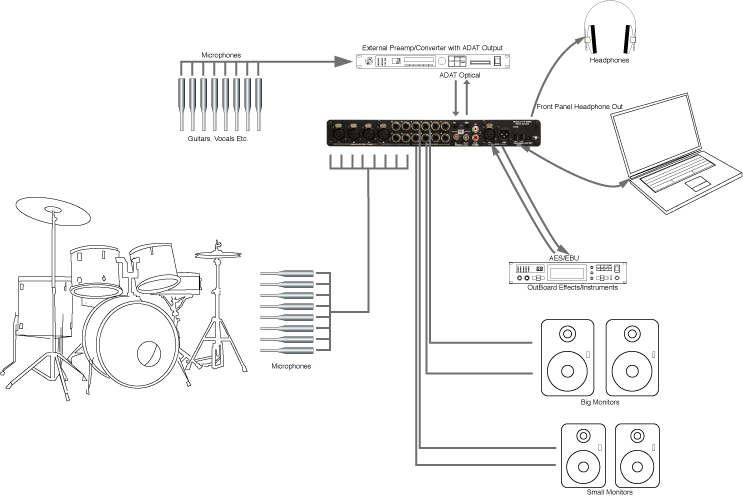
We will start with the “2882 Basic with Monitor Control” template as that configuration gets us most of the way there. The configuration looks like:
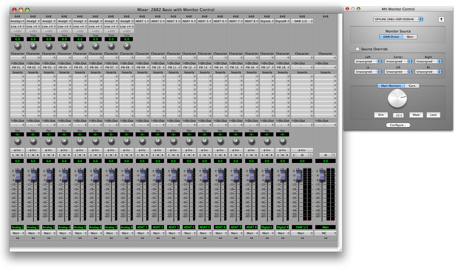
This template configures a single 2882 with:
- All inputs routed to the computer
- All analog inputs set to Line +4 input level
- All inputs routed to a stereo monitor mix
- All inputs to the stereo monitor mix are unmuted
- Stereo Output 1+2 from the computer routed to the monitor mix
- Monitor mixer is routed to the Monitor Controller
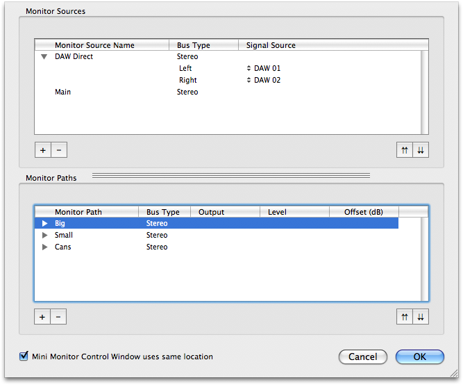
However, the template does not provide support for our scenario of two sets of stereo monitors. So we can quickly add that to the configuration. The Monitor Controller configuration in the template looks like:
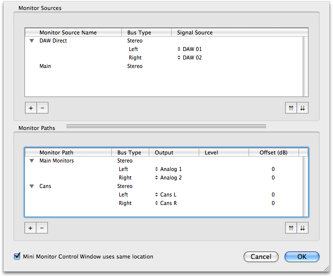
The configuration includes a DAW Direct source that routes directly from the DAW 01 & DAW 02 channels from the computer, and the Main Stereo bus is also available as a source for the Monitor Controller.
The configuration also includes two Monitor Paths for output. One, named “Main Monitors”, routes out to Analog 1+2, and the other, named “Cans”, routes out to the Cans connector on the front panel.
This is pretty close to what we want, but we need to have another Monitor Path for the “Small” monitors, and we want to rename “Main Monitors” to “Big”.
So, first we add another Monitor Path by clicking the + button in the Monitor Paths section:
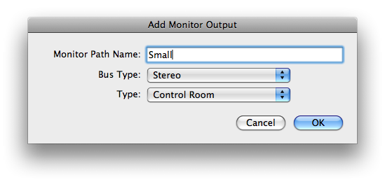
Then select the output channels for the path (click the popup for the Left Channel); hold down the option key to select successive channels in one step:
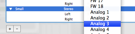
After you make the selection the path will be configured:
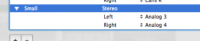
You can close the disclosure arrows for the Monitor Paths list:
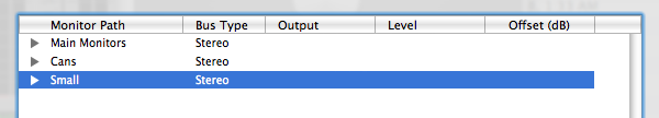
And move the Small Monitor Path to be the second item by clicking the up arrows button:
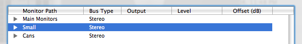
And rename the “Main Monitors” Path to “Big” by double clicking the path, and typing the new name. When you are done it will look like:
After you click the OK button, the Monitor Controller window will look like this:
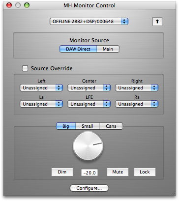
We want to make sure that both Analog 1+2 or Analog 3+4 has signal, but not both at the same time; sound should only come from one set of speakers at a time. That’s precisely what the Monitor Controller will do for us; sound will only be routed to one of the Monitor Paths at a time, and the unselected Monitor Paths will be muted.
To switch between the Big monitors and the Small monitors, all you have to do is click on the path you want to be active in the output selector bar right above the output gain control knob.
If you want to use this example as a tracking set up, choose Save As... from the file menu. This brings up a standard Macintosh save dialog and allows you to save the entire state of MIO Console as a setup document.
Conclusion
The preceding examples should give you a sense of the possibilities that are enabled by the routing and mixing features of Mobile I/O. While this is just a starting point, we have covered all of the basic operations required to manipulate Mobile I/O with complex routing. You should be able to build upon these scenarios to construct routings that suit your needs and your workflow.