Routing Applications for Unexpanded Units
Routing Applications
This document provides a hands-on description of how to configure the mixer and router for a somewhat complex tracking situation. This document is only for un-expanded units (Mobile I/O units that do not have a 2d Card installed). If your unit has a 2d Card installed, the configuration process is very different (and much simpler).
For information about Routing Applications with a 2d Expanded unit, please refer to the Routing Applications for 2d Expanded Units document.
Clocking Considerations
There are five ways that you can clock Mobile I/O:- Internal
- Digital (AES/SPDIF)
- Optical (ADAT/TOSLINK)
- Wordclock
- 256X
Each choice is appropriate for a particular situation. In general, you should use Internal clock if you can because you are likely to find that it makes your other digital gear sound better. However, there are some devices that either must be the clock master or work better if they are the clock master. For these devices, choose the clock port which is most appropriate for the device.
For example, many DAT machines distribute clock over their digital audio connection (AES or S/PDIF). For these machines you would connect to the AES or S/PDIF port on Mobile I/O and choose DigIn (44.1/48) for single rate or DigIn (88.2/96) for double rate in the MIO Console clock source popup. For more information about configuring the clock source, see “System Controls”.
SINGLE SPEED CLOCKING VS. DOUBLE SPEED CLOCKING
The difference between single speed (1x) and double speed (2x) clocking is handled as a fundamental mode change in Mobile I/O. The sample rate does not vary continuously between 48k and 88.2k but changes discontinuously when the double speed mode is set in the hardware.
When Mobile I/O is running on internal clock, this mode change is handled transparently when you specifiy what sample rate the box should use.
When Mobile I/O is running on external clock, it cannot determine in advance which mode to use, so you need to tell it what mode is appropriate for your external clock source. You communicate this information by selecting the proper external clock source. Each external clock source comes in two different flavors:
- xxxx(44/48)
- xxxx(88/96)
where the “xxxx” corresponds to the actual clock source. If you will be clocking off of a 1x source (e.g. 32kHz–50kHz sample rate) then choose the xxxx(44/48) clock source. On the other hand, if you will be clocking off a 2x source (e.g. 64kHz–100kHz sample rate) then you will choose the xxxx(88/96) clock source. If you choose the wrong flavor, Mobile I/O will not lock properly. When you select the flavor, it tells Mobile I/O which mode it has to run in, and the Mobile I/O can lock to the external clock in the appropriate frequency range.
EXAMPLE SETUP
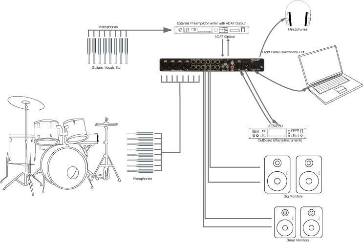
In this section we will go step by step through an application that is possible with a ULN-2 configured as shown in Example ULN-2 Setup above. After reading this section you should have a feel for how to apply Mobile I/O’s routing and mixing capabities.
WHICH DEVICE IS THE CLOCK MASTER
The first consideration involved with a setup like this is which device should be the clock master. If the external device is happy slaving to Mobile I/O then make Mobile I/O the clock master by setting the clock source to internal in MIO Console. Set the external device to lock to its digital input, or wordclock if the external device has a wordclock input. If you use wordclock, make sure to connect a 75 Ohm BNC cable between Mobile I/O and the external device.
If you find that you are getting clicks and pops in the audio coming from the external device, try clocking in the other direction. Set the external device to use its internal clock and set the Mobile I/O clock source to digital or wordclock. Remember to choose the appropriate clock rate (single or double) for the sample rate you will be working at.
Now that all of the digital devices are playing nicely with each other, let’s take a look at some possible applications with this setup.
EFFECTS FOR TRACKING
Many performers (especially singers) find it easier to get a good take if they have some sweetening effects in their headphone mix while tracking. These will usually be temporary effects and will not necesarily make it into the final mix but they can make the difference between a good take and a bad take. In this example, we will be using an effects device connected to Mobile I/O’s AES ports to add some reverb to the headphone mix we make in MIO Console.
SETTING UP THE ROUTING
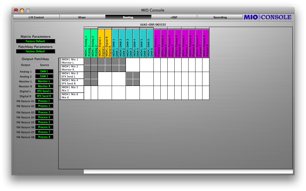
The first thing we need to do is configure our mixers and routing. For this setup we will use two mixers in MIO Console: one for the actual headphone mix and one for the send mix to the reverb. To do this we need to bring up the Mix/Output Routing view in MIO console
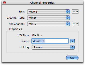
We’ll also assign DAW 1 and 2 to mix busses 1 and 2 for DAW playback. We can name the mix busses by clicking on the mix bus label. This will show the matrix configuration window (Naming the mix busses).
We’ll name the headphone mix Monitor L/R and the send mix Effects Send L/R. You must name each mono bus separately, and the Console will combine the names automatically. You can use the tab key to increment through the mix busses as you name them. When you’re finished, hit the return key to close the configuration window.
The mixer bus names have propagated through MIO Console which means they will now show up in the Output Patchbay and the Mixer view.
Note that Digital L/R is assigned to the Headphone mix but not the Effects send mix. This is critical because Digital L/R is the effects return, and we definitely do not want to assign the return to the send. If we do, we’ll get feedback and no one will be happy, especially the singer.
To route the mixers to their intended destinations we use the Output Patchbay. We want the Headphone mix to feed the front panel headphone output of Mobile I/O so we’ll set the Monitor section of the Output Patchbay to take its input from Monitor L/R
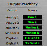
The Effects Send mix should feed the AES outputs so we’ll set the Digital section of the Output Patchbay to take its input from Effects Send L/R.
The routing is now set. We can save the setup for the next tracking session using the Matrix Parameters and Patchbay Parameters popup menus (see “Parameter Popup Controls” on page 50 for details).
Now we’ll switch to the Mixer View.
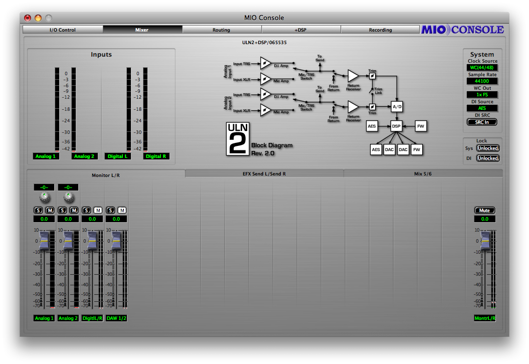
Notice the Mix Tabs on the left are now labeled Monitor L/R and Effect send L/R. Also notice the fader marked Daw 1/2 on the right. We’ll use this fader to control the playback level of the DAW tracks we want to overdub against.
If you have signals running to Mobile I/O you should see activity on both the input meters and the mixer meters.
By default the mixer’s faders are are at unity gain and the mutes are engaged. We can unmute all the mixer channels by holding the option key and clicking one of the mutes. All of the channels will unmute. But for the time being we’ll keep the Digital L/R fader muted.
Now we can set up a dry headphone mix. Once we have basic balances set, we can switch to the Effects Send mixer by clicking its mix tab. In the Effects Send mixer we can unmute each channel and set its send level to the reverb, or we can use the Mixer parameters popup (see “Mixer Pane Tabs” on page 36) to copy the mix from the Headphone mixer to use as a starting point.
To copy mix parameters from one mixer to another:
- Click and hold the mix tab for the mixer you want to copy from. A popup menu will appear:
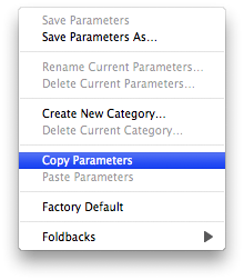 Mixer parameters popup
 - Choose Copy Parameters
- Now click and hold on the mix tab you want to copy to
- Choose paste parameters
- The mix parameters have now been copied
Now we can can go back to the Monitor mixer and unmute the Digital fader. The reverb should now be heard in the headphone mix.
If you want to use this example as a tracking set up, choose Save As... from the file menu. This brings up a standard Macintosh save dialog and allows you to save the entire state of MIO Console as a setup document.
The preceding examples should give you a sense of the possibilities that are enabled by the routing and mixing features of Mobile I/O. While this is just a starting point, we have covered all of the basic operations required to manipulate Mobile I/O with complex routing. You should be able to build upon these scenarios to construct routings that suit your needs and your workflow.
CONTROLLING MULTIPLE MONITORS WITH THE 2882
We can use the routing snapshot features of Mobile I/O to set up multiple monitor paths and easily switch between them.
EXAMPLE SETUP
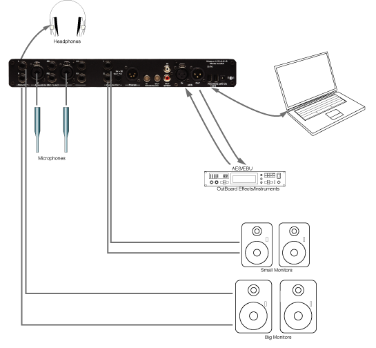
For this example we will have two sets of powered monitors connected to Mobile I/O. The first set will be connected to Analog Outputs 1-2 and the second to Analog Outputs 3-4.
In the routing window we’ll set up a monitor mixer on busses 5 and 6 and name it Monitor L/R. We’ll assign Analog 1-8, ADAT 1-8, Digital L/R and DAW 1/2 to the monitor mixer. This will allow us to monitor playback from a CoreAudio application as well as our live inputs.
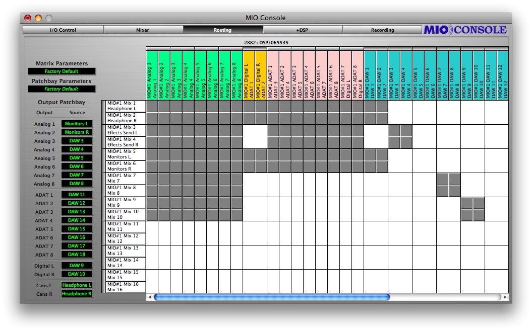
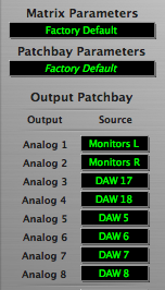
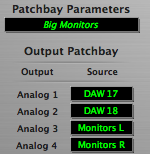
Now in the Output Patchbay we’ll assign Monitor L and Monitor R to Analog 1 and Analog 2. This creates the routing for our Big Monitors. We’ll also make sure to assign an output pair that we know won’t ever have signal on it to Analog 3 and Analog 4. We’ll use Daw 17 and Daw 18.
We want to make sure that Analog 3 and Analog 4 won’t ever have signal in this setup because the Small Monitors are connected to Analog 3 and Analog 4 and we don’t want to have random channels playing through the Small monitors while we are listening to the Big Monitors.
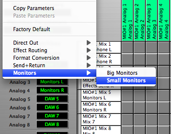
Next we’ll save this routing using the Patchbay parameters popup menu. But first we’ll create a new category by choosing Create new category... from the Patchbay Parameters popup.
A dialog will appear:
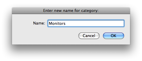
We’ll name the category “Monitors” and click OK.
Now we can save the setup into the Monitors category by choosing Save As... from the Patchbay Parameters popup. A dialog will appear:
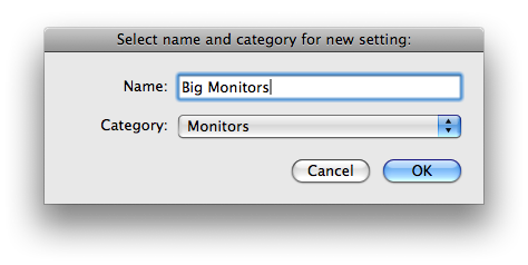
We’ll choose the Monitors category from the category popup, name the setup “Big Monitors” and click OK. The setup has now been saved.
Now we can set up the routing for the Small monitors. To do this we simply assign the monitor mixer to Analog 3 and Analog 4 and assign DAW 17 and DAW 18 to Analog 1 and Analog 2.
We’ll save the setup into the Monitors category as “Small Monitors” using the Parameter Patchbay popup. Now we have a monitor switching system. To switch monitors, simply choose the monitor path you want using the patchbay popup window.